Continue to Site

Welcome to EDAboard.com

Welcome to our site! EDAboard.com is an international Electronics Discussion Forum focused on EDA software, circuits, schematics, books, theory, papers, asic, pld, 8051, DSP, Network, RF, Analog Design, PCB, Service Manuals... and a whole lot more! To participate you need to register. Registration is free. Click here to register now.

Sim900 auto-Power down after network registration

Status
Not open for further replies.
hi,

how can i check that is module registered on a network, whenever i want?
 

use the AT+CREG command...

my modulr is registered to a network,

when i enter "AT+CREG" i get Error,

when i enter "AT+CREG=?" i get +CREG: (0-2) that is the range of input values...

and when i enter "AT+CREG?", it returns +CREG: 1,1...

so how can i check it? would you please explain it?
 

+CREG: 1,1 - the second 1 means "Registered, home network"

you'll find the details in the "SIM900 AT Command Manual" ... look for: AT+CREG Network Registration
 
thanks for reply...

I'm using GPRS to transfer data in internet. and i must keep my connection alive.

you know how can i check my connection whenever i want?

actually i wanna reconnect, if gprs connection is broken!
 
Last edited:

Hello Guys! This thread was a life saver...had the same problem with auto-power down and it was in fact the power supply. Big spikes down to 3.2V! Removing the antenna reproduced the issue every time. Better power supply + cap, worked wonders, so far so good! Thanks to everybody that contributed! Regards!
 

That's great! I've seen guys chase power problems on these radios for weeks, and it doesn't help that some people point them in the wrong direction because they don't understand the issues themselves. As I say in my GSM Developer's Bible; "Your number one priority in GSM-based products should be the design of the power system. You need to pay particular attention to noise and the transient response of your supply. Dips in the power supply that are only nanoseconds long can cause the module to reset. Even power supplies that have proved themselves in Bluetooth and WiFi designs may not be good enough for cellular."
 
  • Like
Reactions: msj121

    msj121

    Points: 2
    Helpful Answer Positive Rating
I am having some problem with my SIM900D, at first its got connected to the network but now it does not connects to the network. I check the AT+CREG command and the result is +CREG:1,3 3 means registration denied. I have this same problem with my old module then I changed the SIM900D SMD it worked fine with my interfacing board. Something is wrong with SIM900D. I have tested the module in other working interfacing board but still it is not connecting to the network. Please help me out :((
 

I am designing a sim900 board right now. I would call myself an amateur at best (even with my computer engineering degree, somewhat useless I now realize).

Does anyone have a simple but efficient power supply circuit? I can use a LiOn battery of course. I saw the schematic on the application note, but it seems somewhat complicated.... Is it the best or are there simpler/better circuits?

I obviously do not want to run into power supply issues.... Also I have seen those nice round super caps on boards, are they connected to vrtc?

The best would be if someone has an eagle schematic already, but I don't mind trying to re-create it in eagle. Like I said, not even an amateur here, just hoping one of my first ventures on my own won't cause me to waste money and time on a bad board.
 

If you are running the module from a LiOn battery you don't need a voltage regulator; you can connect the VBAT pins directly to the battery - this is actually preferred. You only need a regulator if you are using a power supply (like a wall wart) or a battery the puts out more than 4.8V. The layout of your grounds and power lines is critical. I have made several posts on this forum that outline the requirements and recommendations - just search for post from "GSM Man".

Here's a synopsis of what you should be concerned with:
- You need very good grounding on your PCB so that there is very voltage loss and ground-bounce. A full ground plane is highly recommended.

- You need adequate decoupling at the module BAT pins - the caps need to be physically next to the pins. I suggest a low ESR (> 10 mOhm) Tantalum cap in parallel with a .01uF MLC.

- You need a power supply that has very good transient response. The module will draw upwards of 2 A whenever it transmits. The power supply will see a huge change in the load impedance and if the transient response is not good enough its output will dip. You can have a power supply with a 20A output rating and poor transient response and still have problems.

- You need a low impedance power supply line, and your regulator should be as close as possible to the module. Like the ground plane, a full power plane is your best bet. If that's not an option, use as wide a power trace as possible. For short runs, I'd suggest at least 80-100mils.

Also, you may want to check out this video: https://www.youtube.com/watch?v=iAU_6HthM0U
 
Last edited:
  • Like
Reactions: msj121

    msj121

    Points: 2
    Helpful Answer Positive Rating
If you are running the module from a LiOn battery you don't need a voltage regulator; you can connect the VBAT pins directly to the battery - this is actually preferred. You only need a regulator if you are using a power supply (like a wall wart) or a battery the puts out more than 4.8V. The layout of your grounds and power lines is critical. I have made several posts on this forum that outline the requirements and recommendations - just search for post from "GSM Man".

Here's a synopsis of what you should be concerned with:
- You need very good grounding on your PCB so that there is very voltage loss and ground-bounce. A full ground plane is highly recommended.

- You need adequate decoupling at the module BAT pins - the caps need to be physically next to the pins. I suggest a low ESR (> 10 mOhm) Tantalum cap in parallel with a .01uF MLC.

- You need a power supply that has very good transient response. The module will draw upwards of 2 A whenever it transmits. The power supply will see a huge change in the load impedance and if the transient response is not good enough its output will dip. You can have a power supply with a 20A output rating and poor transient response and still have problems.

- You need a low impedance power supply line, and your regulator should be as close as possible to the module. Like the ground plane, a full power plane is your best bet. If that's not an option, use as wide a power trace as possible. For short runs, I'd suggest at least 80-100mils.

Also, you may want to check out this video: https://www.youtube.com/watch?v=iAU_6HthM0U

Thank you so much. A couple of clarifications for the amateur in me:

MLC = MultiLayerCeramic Capacitor?
The Tantulum Cap should be how many Farad? 100nF?

I intend on using the LiOn batteries for ease of design then, I assume if they are desired they will have no problem with transient response. Further, as the LiOn battery drains I assume the Voltage goes down, would I still need a power regulator in the case it goes below voltage for that? Or should I simply just require re-charging? I assume also if I build a standard charging circuit it should not affect the sim900.


Also, while I am asking question, I put the antenna directly beside the chip port, and was told that if it is close enough it will not require a matching circuit, have you heard this before? Otherwise, I am quite stumped how to design the matching circuit.


Thank you again for your help. I will in the mean-time continue looking through your posts, very informative.
 

- Yes, MLC stands for Multi-Layer Ceramic. The Tantalum should be at least 100mF. Some people have told me they've used a 100uF MLC in place of the .01uF MLC & Tantalum, but I haven't tried that myself.

- When using a battery, just make sure the wires between the battery and board are not too long (probably 3" max) or too thin a gauge. I was once called in to troubleshoot a design that had intermittent problems with battery leads that were 6" long. Once we shortened the leads the problems went away.

- If you want to run on batteries with a voltage below 3.6V you could use a boost-regulator to increase the voltage. However, I doubt the battery would have enough capacity left to supply the current required. Also, there are a lot of issues you need to deal with when designing that type of regulator. The easiest thing to do is to make the batteries replaceable and charge them off-line.

- If the antenna connector is far from the module then the traces between the module & antenna have to be 50 ohms. You can do this using a "micro-strip" layout. However, if the trace is short enough you don't need to be concerned with that . Just place the connector as close as possible to the antenna pin of the module and use a 20-30 mil trace to connect them. If you use a HFL or UFL connector for the antenna the trace between the pin and connector can be less than 30 mils.
 
  • Like
Reactions: msj121

    msj121

    Points: 2
    Helpful Answer Positive Rating
- Yes, MLC stands for Multi-Layer Ceramic. The Tantalum should be at least 100mF. Some people have told me they've used a 100uF MLC in place of the .01uF MLC & Tantalum, but I haven't tried that myself.

- When using a battery, just make sure the wires between the battery and board are not too long (probably 3" max) or too thin a gauge. I was once called in to troubleshoot a design that had intermittent problems with battery leads that were 6" long. Once we shortened the leads the problems went away.

- If you want to run on batteries with a voltage below 3.6V you could use a boost-regulator to increase the voltage. However, I doubt the battery would have enough capacity left to supply the current required. Also, there are a lot of issues you need to deal with when designing that type of regulator. The easiest thing to do is to make the batteries replaceable and charge them off-line.

- If the antenna connector is far from the module then the traces between the module & antenna have to be 50 ohms. You can do this using a "micro-strip" layout. However, if the trace is short enough you don't need to be concerned with that . Just place the connector as close as possible to the antenna pin of the module and use a 20-30 mil trace to connect them. If you use a HFL or UFL connector for the antenna the trace between the pin and connector can be less than 30 mils.

Hey GSM-Man, I am learning an enormous amount right now from this and the other posts.

1). I will for now simplify and run from LiOn 4.8V battery, short wires, and drop the voltage for my micro-controller if needed.
2). I will definitely try to avoid the micro-strip and use a 20-30mil line if possible, simplicity for me is key. I have an SMA connector with a 25 mil trace, is that okay?
3). For the ground plane/voltage plane, I noticed that on the bottom of the chip there looks to be an exposed grid of dots, should these touch the ground plane, is it bad? voltage plane? I can try to not have the plane in the center of the chip if necessary.
4). That Tantalum cap that you mention at 100mF (is that Micro Farad or MilliFarad, I didn't really see any of the latter on digikey as quick search), is it a typo and uF? or nF?
5). Just to make sure, I connected the RI out from the chip to my interrupt, but all the other pins for communication (dtr, dcd, dsr, cts, rts) can be connected to any i/o pins on my micro? ofcourse tx to rx and rx to tx (I just want to double check).
6). I saw in the application note to use a large capacitor, are there any other specs you would suggest?

Thank you so much again!
 

2 - You can certainly use an SMA connector
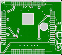
3 - You need to keep the exposed pads on the bottom of the SIM900 free of any copper. You need to place "keep out areas" in the plane under those pads. I usually put a ground plane under the module with connections to the module's ground pins. I then place a lot of vias between that plane and the full ground plane.. Below is an image of a typical layout I use.


4 - The cap value was a typo - should be 100uF.
5 - Correct on the pin connections
6 - The cap must have a low ESR (<100 milliohms) - here's one on DigiKey that meets the spec:https://www.digikey.com/product-detail/en/TPSD107K010R0100/478-1777-1-ND/564809
 
  • Like
Reactions: msj121

    msj121

    Points: 2
    Helpful Answer Positive Rating
2 - You can certainly use an SMA connector
3 - You need to keep the exposed pads on the bottom of the SIM900 free of any copper. You need to place "keep out areas" in the plane under those pads. I usually put a ground plane under the module with connections to the module's ground pins. I then place a lot of vias between that plane and the full ground plane.. Below is an image of a typical layout I use.


4 - The cap value was a typo - should be 100uF.
5 - Correct on the pin connections
6 - The cap must have a low ESR (<100 milliohms) - here's one on DigiKey that meets the spec:https://www.digikey.com/product-detail/en/TPSD107K010R0100/478-1777-1-ND/564809

Its 2 a.m. I just am stopping to work on the design, so much fun, now that I feel a little bit more confident with your help. Btw, thank you for the suggestion on the cap. A couple quick questions:
1). Will the ground plane and voltage plane cause some magnetic interference with a 2 layer board. If you haven't had issues I think that is good enough for me, but just curious.

2). Can I use one set of capacitors for the 3 voltage pins on the chip as they are side by side and I can just connect them together? (Originally I had more than one set).

3). I think I might go with the one mlcc as it is so much smaller, but if you advise against I can try to rework the design, I researched the difference for a bit and it seemed like for decoupling the mlcc is a good choice https://www.dataweek.co.za/news.aspx?pklnewsid=27008. Though the person seems a little too sure mlcc is the right choice. I think I switched all the caps to mlcc after, except the vrtc of course.
 

1 -I'm not sure what you mean by "ground plane and voltage plane cause some magnetic interference with a 2 layer board". I've used 2-layer, 4-layer and 6-layer boards with these modules. The choice has more to do with the how constrained you are on size and component density than anything else. The board that I took that image from contains a SIM900, GPS receiver, microcontroller, SIM card holder, voltage regulator, 2 antenna connectors and 2-dozen discrete components, all on a board that measures 1.1" x 2.6". It wouldn't be possible to put all those parts on a 2-layer board that size and have an adequate ground plane.

The important thing is that you have low-impedance power traces and a "good" ground plane; one that has a low enough impedance at frequencies into the GHz range to minimize noise. A large contiguous ground plane is best, and typically a 4 (or more) layer board allows you to easily do that. A 2-layer board requires a bit more care in your layout. You want to make sure the the power and ground connections between the module and your battery are as short and "fat" as possible.

2 - One cap for the 3 Vbat pins is fine. If you look at the lower-right corner of my board image you'll see the 3 power pins, a single tantalum cap, and a terminal for the battery (there's a .01uF cap of the back side of the board). BTW - J3 is the antenna connector.

3 - Typically, the reason a tantalum cap in parallel with a ceramic cap has been used is due to cost and availability. Until fairly recently, large value MLCC caps have been hard to find and have been costly. Now you can get a 100uF MLCC for about the same price (maybe even cheaper) than the cost of the 2 caps. If you use an MLCC, you do need to pay attention to the dielectric used, as pointed out in the article you cited.
 
  • Like
Reactions: msj121

    msj121

    Points: 2
    Helpful Answer Positive Rating
Well, I wanted to let you know I ordered the board, hopefully it will turn out properly, I decided to go with two ground planes and a nice thick vbat pin. Re-arranged somethings to put it right beside the pin of the chip. Pretty excited to see how this will work out.

Thanks for all of your help!
 

I definitely made a mistake not checking digikey for 100uF MLCC for the power pins.... Not sure where to find this capacitor... I am currently trying to get some from alibaba, though that might be a risk in quality if I can find it, we shall see.

I might need to sneak an 100uF 0805 tantalum with 0.01uF MLCC on somehow.... Is an 100uF 0805 Tantalum alone enough? Or should I try to put them in parallel?

Just curious, do you think I could solder them bottom to bottom (to put them in parallel) and then solder the sides to the pad (instead of the bottoms)? Ugh... Design mistakes are the worst.
 
Last edited:

I definitely made a mistake not checking digikey for 100uF MLCC for the power pins.... Not sure where to find this capacitor... I am currently trying to get some from alibaba, though that might be a risk in quality if I can find it, we shall see.
Digikey: https://www.digikey.com/product-detail/en/JMK316BJ107ML-T/587-1963-1-ND/1646626

I might need to sneak an 100uF 0805 tantalum with 0.01uF MLCC on somehow.... Is an 100uF 0805 Tantalum alone enough? Or should I try to put them in parallel?
The tantalum alone is NOT sufficient.

Just curious, do you think I could solder them bottom to bottom (to put them in parallel) and then solder the sides to the pad (instead of the bottoms)? Ugh... Design mistakes are the worst.
I don't know about that - it may work.
 
  • Like
Reactions: msj121

    msj121

    Points: 2
    Helpful Answer Positive Rating
Wow! I had been looking and filtering for an mlcc in 0805, I think I must have checked 2/3 times, I guess I was in the wrong section or made a mistake. Haza!

I just tried filtering again, I realized I was making such a stupid mistake! I scrolled to the bottom and saw it stopped at uF and didn't go to nF, I kept getting confused.... For some reason I think nano is bigger, which I always correct myself as being stupid since nano-technology is pretty new, and micro scopes are pretty old!

Thank you for snapping me out of it. Btw, I found on alibaba a 100uF 0603 MLCC for about $0.1 If I order 25, do you think that its too good to be true, someone told me it is, and I think it might be, but I am just hoping.... https://szgoldtech.en.alibaba.com/p...9/orginal_SMD_capacitors_100uf_6_3V_0603.html

Well I will probably order the 0805 just in case. Btw what is the reason you buy your caps from Taiyo Yuden instead of TDK the first one listed, like an ignorant person like me might do? I know (as you could tell) nothing about corporations, but I have learned so much more now just in these few posts.

Thank you again.
 

Status
Not open for further replies.

Part and Inventory Search

Welcome to EDABoard.com

Sponsor

Back
Top