Continue to Site

Welcome to EDAboard.com

Welcome to our site! EDAboard.com is an international Electronics Discussion Forum focused on EDA software, circuits, schematics, books, theory, papers, asic, pld, 8051, DSP, Network, RF, Analog Design, PCB, Service Manuals... and a whole lot more! To participate you need to register. Registration is free. Click here to register now.

SIM300 breakout PCB design - let's fab some PCBs :)

Status
Not open for further replies.
sim300d eagle

hi sabeti_1990
u have add 2 element's betwin rxd txd mega 64 and sim 300
and don't wrote what is this
i use sim 300cz
but i can only send data whith micro and don't recive from sim300
what's the problem?

can u help me?

why i cant reecive data from sim300 to micro but can recive from sim 300 in pc
 

sim300cz library

hi,

works the sim300 without a SMF05C ??? I only want to do some tests with the sim300. Is it possible to communicate only over tx and rx ?
 

sim300_v7

Is there a standard ribbon connector available that we can use to connect a SIMCOM to a breadboard/PCB?

I have a SIMCOM548C. This has a 60 pin connector. I have the female SMD connector for it which looks like its going to be pretty hard to hand solder.

However, the female connector looks a lot like the connector you get on a lot of flat ribbons. I'm thinking if an appropriate ribbon connector can be plugged in the the ribbons wires can be connected easily to the PCB/breadboard (I only need about a quarter of them)

Anyone know if this is possible? Know where you can buy ribbon connectors from?
 

pcb layout sim300d

I have a Question about the Layout considerations
Is it required to create a Ground plane on the PCB under the Modules position?
Is it recommended to connect the shield to this Groundplane?

An other thing is the usage of only the std Serial interface(not Debug) with RXD/TXD & GND,
has to be taken care of any consideration about leaving the other Pins (RTS...)?

Thank you for information!
 

Re: sim300_v7.02

sabeti_1990 said:
hi every one
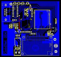
It's a pcb of sim300c + atmega64 that I make it. it works good
hope it's useful
if U want another tell me
be success


Grateful
could you explain more about this PCB?
 

hi, with my personal experience, this is bad design. The case for the voice communication process, is unstable. Using single-sided PCB to connect GSM module is a very bad way.

Recommend to you a sim300 + avr (atmega8) + usb experimental development board:
**broken link removed**
 

hi everybody, i am design a project for sim 300cz in my school.
the same it(sim300c).i dont find datasheet of module 300cz.
can u help me?
hurry up!
thanks everybody very much!
 

you can explain about pcb and give me pcb
email:truong_giang2211@yahoo.com
thanks you very much!
 

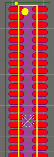
i design the pcb for 60 pin connector

8_1265278388.jpg


you can download from
https://www.2shared.com/file/11113445/cca145f3/GSM_60PIN_CONNECTOR.html

Added after 6 minutes:

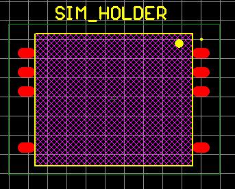
and design sim holder pcb

26_1265279105.jpg


download from

https://www.2shared.com/file/11113591/7fa09590/SIM_HOLDER.html
 
how I can read sms with at command in code with micro (not hyper terminal)?
and how I can detect Enter (CR) ?

Thanks
 

Look at the source code towards the end:

**broken link removed**

**broken link removed**
 

Hi Friends,
I would appreciate if someone provide me the PCB design for SIM300CZ EVB..... Thx

Regards,
Ali Ahmad
 

Hi all,
I am doing a project using SmartTM1 GSM module. May I know anyone have done with this GSM module before coz I cannot find user manual of this module.
Thankx alot.
Quang Tien
 

Good work gentlemen, now that the connectors can be plugged into an Eagle design the last step to make this a truly beneficial effort for all those EVB seekers is to publish the gerber files so anyone can easily send them to a cheap Chinese fab house and make the boards with zero effort.

Anyone ready with gerbers for a simple break-out PCB for that module?
 

Re: sim300 module

Hi !
I was looking for the SIM300s footprint. Thanks as the footprint you provided will reduce my pain for creating Demo board for SIM300s.

Thank you once again!
 

your pcb is not opening with expresspcb.

how to open and use it?
 

Re: sim300 atmega source code

I got some 74LS573, LM393 and LM358 among others in my circuit that interfaces a µC to SIM300 module. I'm planning to route the pcb myself and i need some advice on how to go abt it.
Tha SIM300 datasheet did mention sparsely on having a separate digital and analogue ground. Do i need to have two different grounds? Do i need to group all digital ICs together using a single ground and then route it to a single point with another lumped analogue ICs ?
By the way, i'm using only a two layer board.

The evaluation kit had the entire area where the SIM300 module sits solder masked. Is that recommended?

hello sir
here you have mentioned about digital ground and analog ground. so i am also getting confused we shud separate tthem or join them and what they make eeffect.
please guide me
 

Re: eagle library sim300

Hi,
I just wanted to know if you really design this PCB... it looks great.
Im trying to design a good pcb for a sim module also... could you give me some tips... Would you share the pcb files ?
Thanks a lot...
(Did you create the pcb and do the assembly or an external company ???)
Thanks again


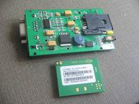
Hi, here is the photo for SIM300 module. We developed a series of breakout PCB for GSM/GPRS modules. Like MC55, Sim300/300C, GR64 etc.

Link:
 

To this date no one has posted a link of something real meaning a true design that works in the real world or even someone who sells the boards?
 

Status
Not open for further replies.

Part and Inventory Search

Welcome to EDABoard.com

Sponsor

Back
Top