Continue to Site

Welcome to EDAboard.com

Welcome to our site! EDAboard.com is an international Electronics Discussion Forum focused on EDA software, circuits, schematics, books, theory, papers, asic, pld, 8051, DSP, Network, RF, Analog Design, PCB, Service Manuals... and a whole lot more! To participate you need to register. Registration is free. Click here to register now.

[SOLVED] Signal distribution using transistor .................

Status
Not open for further replies.
oh :O G_current is Icbo ? Rb = ( Vcc - 2*Vf ) / ( Ic / G_current + 2*Vf / R3 ),with this we dont have to bother keeping R3 right :) ?
-
hmm... so,do u suggest not keeping r3? Icbo wouldnt effect much ?
-
also,we dont have to lower R3 much ..as long as it drives 0.1μAdc current across it.. 1k to 3k ohm resistance should do i guess!!
 
Last edited:

Did you read this ;)

Added:
I agree with you, it is not a good practice allowing the base of a transistor to float anytime.
But lowering the value R3 requires more current from the input source (about Vbe/R3 more). Vbe=0.75V if 1 transistor, 1.5V if two cascaded ones

I meant R3 should be added if the input source could be open circuit. And there are some advantages in adding R3 not important here.

R3 value is not critical but it should be included in the R1 formula.
I usually let the current in R3 be about 0.05 to 0.2 (5% to 20%) of the total current from the input source
 
  • Like
Reactions: kdg007

    kdg007

    Points: 2
    Helpful Answer Positive Rating
haha,i didnt see you have updated the previous post :) ok i want to add R3 , now from the start..for Ic to get 180mA(18 ma for each white LED),Ib = 180mA/10*20 = 0.9mA .R1 = 3.9k ( 806uA current to the base) ,so R3 should be more than that ----- 10k (1335 uA current across it) ? hmm
R1=Rb - Rs ( what is Rs here ?)
 
Last edited:

please read #23 post ,i have updated it.tell me if i am wrong
 

Please note that our calculations are approximated so what we get as values are just for a good start and can be ok even if they are not exactly satisfying our formulas.
For example we assumed Hfe = 200 but its real value could be 250 for example.
So when we design a circuit, it is normal that we try getting approximated values first from which we can start and see the best values for the real circuit taking into account the variation of the parameters. In your case, the worst thing that could happen is getting a bit lower LED current than expected (no one will be hurt ;) )


For instance, you can decrease 3.9K to 3.3K so that R3 could be decreased too.

Also you can always do your calculations backwards when some or all components are specified like R1 and R3.

Added:
When you understand the basic formulas and you know how to solve an equation (or simultanuous ones), the design becomes like charging a capacitor which gradually reaches its full charge, second after second... in my case, it is be day after day... if not month after month ;)
 
Last edited:
  • Like
Reactions: kdg007

    kdg007

    Points: 2
    Helpful Answer Positive Rating
yes,i agree with you,after we get the proper values i want to see in the simulator and see the results :)
for Rc = (5-3.3-1.1)/18mA = 33 ohms for each LED .


for calculating Rb =Rb = ( Vcc - 2*Vf ) / ( Ic / G_current + 2*Vf / R3 ) === (5-1.5)/([180mA/0.1ua]+[1.5/10k]) = 0.1uA :O ..... i might be miss read the formula
 

Rb =Rb = ( Vcc - 2*Vf ) / ( Ic / G_current + 2*Vf / R3 ) === (5-1.5)/([180mA/200]+[1.5/10k]) = 3.5 k ohms for Rb
R1 = Rb-Rs = 3.5k ,
R3 = 10k,
Rc=33 ohms.... this should be right ???
 

For 10 LEDs I guess... It is a good start to simulate the circuit.
Please remember, the simulation results are always right but based on the component models used. The final check should be done on a real circuit so that one can see if some adjustments are needed to get what the project is made for.
 

idea 1.jpg
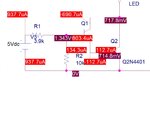
as per our calculations,when you see the base current for Q1 its 803.4ua but Q2 is getting 112.7uA. do we have to consider the combined Base current in Darlington circuit ?
thank you for providing more info..really helpful :)
 

yes..but i can add more LEDs(each having separate resistors) ,since we discussed for 10 ..

---------- Post added at 15:44 ---------- Previous post was at 15:39 ----------

ya,i am getting proper base current with 10leds :) i`ll try out building this circuit ,.,..lets see :)
 

When you will add the 10 LEDs you will find the Ib of the two transistors almost equal as you expect.
With one LED, hence about 29mA only ... the actual base current is rather very high so it splitted in Q1 to E and C (here Ib=Ie+Ic). Normally Ib = Ie-Ic
 
  • Like
Reactions: kdg007

    kdg007

    Points: 2
    Helpful Answer Positive Rating
darlington.jpg

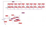
as per our calculations ,the simulation results showing 29mA across each LED(LED replaced by VDC ,since i cannot find LED with Vf of 3.3v).but in practical,the current through each LED is 1.4mA (measrued using current meter).
 
Last edited:

Let us focus on the real circuit.
Did you measure Vcc? I mean, is it 5Vdc?
If it is 5Vdc, are you sure the voltage ripple is small? If you are using 7805 then there is no ripple.

Did you measure Vce?

Please remember that you can always start with one LED then add one after another and see where the weak node is and when it shows up.

Keep tuned...
 
Last edited:

This isn't a good way to design a circuit. Current gain varies a lot from one transistor to another, and also changes with temperature, so it's not a good parameter to rely on.

I'm still not sure what you're trying to do. If the supply voltage is fixed at +5V, and you want the LEDs to always be on with a certain current through each, then there is no need for any transistors. You can just use a resistor in series with each LED.

I can think of two reasons to use transistors:
  • You want to switch the LEDs on and off using some other circuit e.g. a microcontroller.
    In this case the transistor acts only as a switch. It does not determine how much current flows; that is still determined by the resistors.
  • The supply voltage is variable e.g. it may be anywhere between 5 and 9volts.
    In this case you need to use a constant current source. A ring-of-two circuit would be good.
 

the 5vDC supply is from a voltage regulator.Vce is showing 2.1v
-
i want to switch the LEDs on and off using some other circuit .but for now i am concentrating on this circuit.

- - - Updated - - -

darlington.jpg
i went back to the single LED...as you can see in the uploaded picture the values are shown... these are my practical values measured.

Vce=873mV
Led Vf = 3.2v
Ic = 11mA
 

Rs = (Vcc - Vled - Vce) / Ic
Rs = (5 - 3.2 - 0.873) / 11 = 84 Ohm

Does your current limiting resistor have a close value as above?

The idea is to verify always what the basic formulas give as results and what we measure on the real circuit. Both they should give almost same values. This is how I design any circuit and this is how I discover my mistakes in applying the formulas and/or building the circuit ;)
 
Last edited:

ok---i rechecked the whole circuit..there is a default in onE of the transistors..i replaced it..now i am getting proper values :) but i am getting 13ma across each LED(10 leds circuit).(LED vf = 3.3v)Vce=824mV.
-
how can the voltage drop across LED can change from 3.2 to 3.3 v ?
how can i get 20mA across the LED ? i have taken VBE = 2*0.75 = 1.5
vce=1.1
 

Status
Not open for further replies.

Similar threads

Part and Inventory Search

Welcome to EDABoard.com

Sponsor

Back
Top