Continue to Site

Welcome to EDAboard.com

Welcome to our site! EDAboard.com is an international Electronics Discussion Forum focused on EDA software, circuits, schematics, books, theory, papers, asic, pld, 8051, DSP, Network, RF, Analog Design, PCB, Service Manuals... and a whole lot more! To participate you need to register. Registration is free. Click here to register now.

Septum polarized Dudes

Pablo_UDEC

Newbie level 6
Newbie level 6
Joined
Oct 1, 2024
Messages
12
Helped
0
Reputation
0
Reaction score
1
Trophy points
3
Visit site
Activity points
163
Hi designers' community,

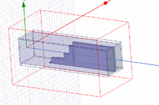
I have some good news. Regarding my project on a septum polarizer with stepped impedance matching, I've obtained the following results. These simulations were conducted as a simple initial analysis.

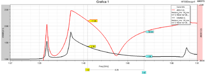
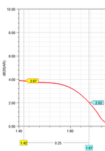
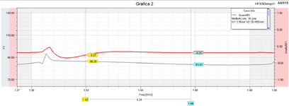
Graph 2: The red plot represents the amplitude difference calculated as dB10normalize(1−mag(S(3:1,3:1)⋅S(3:1,3:1)))dB10normalize(1 - \text{mag}(S(3:1,3:1) \cdot S(3:1,3:1)))dB10normalize(1−mag(S(3:1,3:1)⋅S(3:1,3:1))), while the black plot shows the phase. I also have another equation for amplitudes: dB20normalize(mag(S(1,3:1)/S(1,3:2)))dB20normalize(\text{mag}(S(1,3:1) / S(1,3:2)))dB20normalize(mag(S(1,3:1)/S(1,3:2))). Do these equations make sense?

In the Second figure, I show the isolation in dB and the VSWR (Voltage Standing Wave Ratio) for ports 3:1 (title of Graph 1). The isolation is quite poor.

I would really appreciate any suggestions and recommendations. Thank you!
 

Attachments

  • 1732650931117.png
    1732650931117.png
    32.9 KB · Views: 39
  • 1732651133433.png
    1732651133433.png
    39.3 KB · Views: 36
  • 1732651204573.png
    1732651204573.png
    61 KB · Views: 39
Hi Pablo,

A couple suggestions: Your model seems overly complicated, you do not need an air box around your polarizer as it is completely enclosed in metal except for the ports. For the septum make it as thin as can be fabricated and you do not need more than 4 steps to get a very good performance. In fact, you could probably get a very good performance with 3 steps as your bandwidth only appears to be 8%.

The only real equations you might need is the one that computes the axial ratio, if you're interested I can post that info. The other parameters are just the s-parameters: return loss, port-port isolation and most importantly the S21 from one of the input ports to your common port. You want to look at both the magnitude and phase from the input to common port, particularly the difference between the two fundamental modes at the common port for the phase response.

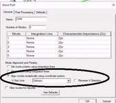
Can you tell me the dimensions of your common port? And also provide a screen shot of how you define the modes in your common port, it should look something like the picture below, notice the selection on how to align the modes at the common port.

Hope this helps
 

Attachments

  • common_port.jpg
    common_port.jpg
    28.5 KB · Views: 23
Hola Pablo,

Un par de sugerencias: tu modelo parece demasiado complicado, no necesitas una caja de aire alrededor de tu polarizador ya que está completamente encerrado en metal a excepción de los puertos. Para el septum hazlo lo más fino que puedas y no necesitas más de 4 pasos para obtener un muy buen rendimiento. De hecho, probablemente podrías obtener un muy buen rendimiento con 3 pasos ya que tu ancho de banda solo parece ser del 8%.

Las únicas ecuaciones reales que podrías necesitar son las que calculan la relación axial. Si te interesa, puedo publicar esa información. Los demás parámetros son solo los parámetros s: pérdida de retorno, aislamiento puerto-puerto y, lo más importante, el S21 desde uno de los puertos de entrada hasta el puerto común. Debes observar tanto la magnitud como la fase desde la entrada hasta el puerto común, en particular la diferencia entre los dos modos fundamentales en el puerto común para la respuesta de fase.

¿Puedes decirme las dimensiones de tu puerto común? Y también proporcionar una captura de pantalla de cómo defines los modos en tu puerto común, debería verse como la imagen a continuación, observa la selección sobre cómo alinear los modos en el puerto común.

Espero que esto ayude
Hi Koba, thank you for your suggestions.


It seems to me that my configuration is just a variation of your screenshot. I defined integration lines for both principal modes (TE01 and TE10), but what is the correct characteristic impedance Z0Z_0? I’ve read in the HFSS forums that there are issues with the correct impedance graph value, especially due to port configurations.


My common port and its value are: 113 mm for a cutoff frequency of 1.32 GHz and f0=1.54 GHzf_0 = 1.54 \, \text{GHz}, as it is a square waveguide. I’m still having issues with isolation, mainly because I don’t know how to solve the stepped design, the stepped transformer. However, I’ve been working on refining the results, because I also don’t know what coaxial radii to use to improve the isolation between the ports. The axial ratio information would also be extremely helpful.
 
You do not need to worry about the impedance of the ports, the important thing is to defined the two principal modes as you have done. To help get a better performance you can try enlarging the square dimension so that you move further away from the cutoff frequency, just be sure that TE11 and TM11 do not propagate.

I am not sure what you mean by solving the stepped design. I assume you have parameterized your model and are letting the computer do the optimization work, this is not a circuit you want to solve by hand. You do not need any radii to improve performance but you do need to take them into account due to the manufacturing process. Ideally, you wouldn't want any radii in your geometry.

The equations for the axial ratio can be found below, just be sure to add the dB20 as shown in the axial ratio plot.

1734498314633.png


1734498394942.png
 
No es necesario preocuparse por la impedancia de los puertos, lo importante es definir los dos modos principales como lo ha hecho. Para ayudar a obtener un mejor rendimiento, puedes intentar agrandar la dimensión cuadrada para que te alejes más de la frecuencia de corte, solo asegúrate de que TE11 y TM11 no se propaguen.
No estoy seguro de lo que quieres decir con resolver el diseño escalonado. Supongo que has parametrizado tu modelo y estás dejando que la computadora haga el trabajo de optimización; este no es un circuito que quieras resolver a mano. No necesitas ninguna radio para mejorar el rendimiento, pero sí debes tenerlos en cuenta debido al proceso de fabricación. Lo ideal sería que no quisieras ninguna radio en tu geometría.

Las ecuaciones para la relación axial se pueden encontrar a continuación, solo asegúrese de agregar dB20 como se muestra en el gráfico de relación axial.

[ADJUNTO]196058[/ADJUNTO]

[ADJUNTO]196059[/ADJUNTO]

Thank you for your patience and understanding, Koba. I’m just a humble student trying to carry out this project. I’m attaching my port configurations. Indeed, my simulation includes parameters for each geometry; however, for optimization using Optimetrics, I haven’t set it up with actual optimization functions. Instead, it only consists of “Mode and Phase Calculations,” the same ones used to view the results. I’m also attaching an example: Port 1 is on the right, Port 2 is on the left, and Port 3 is the common port.
1734617958076.png
1734617565687.png
1734617615601.png
1734617638685.png

1734618173658.png
 

Attachments

  • 1734618076124.png
    1734618076124.png
    13.2 KB · Views: 9
Hi Pablo,

Your common port looks good. I do not understand why ports 1 and 2 are circular? Shouldn't they be rectangular ports with the dimensions: a=113mm and b=(113mm-septum_thickness)/2 ?

Usually there are 3 optimization goals for a septum polarizer:
1. return loss: S(1,1)
2. port-port isolation: S(2,1)
3. delta phase: cang_deg(S(3:1, 1)) - cang_deg(S(3:2, 1)) = +/-90deg

If you use a 4 step septum then there will be 8 optimization variables. I like using the "sequential nonlinear programming" optimizer and sometimes the "quasi-newton".
 
Hola Pablo,

El puerto común que tienes parece bueno. No entiendo por qué los puertos 1 y 2 son circulares. ¿No deberían ser puertos rectangulares con las siguientes dimensiones: a=113 mm y b=(113 mm-espesor del tabique)/2?

Generalmente hay 3 objetivos de optimización para un polarizador de tabique:
1. pérdida de retorno: S(1,1)
2. Aislamiento puerto-puerto: S(2,1)
3. fase delta: cang_deg(S(3:1, 1)) - cang_deg(S(3:2, 1)) = +/-90deg

Si utiliza un septum de 4 pasos, habrá 8 variables de optimización. Me gusta utilizar el optimizador de "programación no lineal secuencial" y, a veces, el "quasi-newton".
Hi Koba, I have already obtained the desired results using the rectangular ports. From my perspective, and although I could be wrong, I consider this way of representing the ports in a rectangular form to be the "easiest" way to perform the analysis. However, the design was always intended to incorporate coaxial ports. Unfortunately, by doing so, the values obtained were not the same or similar to those expected, so I am currently working on improving this aspect.
 

LaTeX Commands Quick-Menu:

Part and Inventory Search

Welcome to EDABoard.com

Sponsor

Back
Top