Pablo_UDEC
Newbie level 6

Hi designers' community,
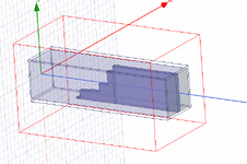
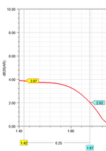
I have some good news. Regarding my project on a septum polarizer with stepped impedance matching, I've obtained the following results. These simulations were conducted as a simple initial analysis.
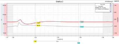
Graph 2: The red plot represents the amplitude difference calculated as dB10normalize(1−mag(S(3:1,3:1)⋅S(3:1,3:1)))dB10normalize(1 - \text{mag}(S(3:1,3:1) \cdot S(3:1,3:1)))dB10normalize(1−mag(S(3:1,3:1)⋅S(3:1,3:1))), while the black plot shows the phase. I also have another equation for amplitudes: dB20normalize(mag(S(1,3:1)/S(1,3:2)))dB20normalize(\text{mag}(S(1,3:1) / S(1,3:2)))dB20normalize(mag(S(1,3:1)/S(1,3:2))). Do these equations make sense?
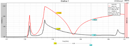
In the Second figure, I show the isolation in dB and the VSWR (Voltage Standing Wave Ratio) for ports 3:1 (title of Graph 1). The isolation is quite poor.
I would really appreciate any suggestions and recommendations. Thank you!
