Continue to Site

Welcome to EDAboard.com

Welcome to our site! EDAboard.com is an international Electronics Discussion Forum focused on EDA software, circuits, schematics, books, theory, papers, asic, pld, 8051, DSP, Network, RF, Analog Design, PCB, Service Manuals... and a whole lot more! To participate you need to register. Registration is free. Click here to register now.

Scoping high side transistor of Two Transistor Forward.

cupoftea

Advanced Member level 5
Joined
Jun 13, 2021
Messages
2,732
Helped
54
Reputation
108
Reaction score
116
Trophy points
63
Activity points
14,450
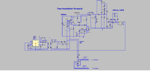
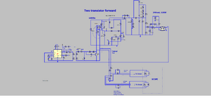
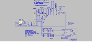
When scoping the gate of the high-side transistor of an offline Two Transistor Forward (2TF),
I usually use a DIY (x1) coaxial probe, but with the 2TF powered through an isolation transformer,
so that the probe doesn't blow up the 2TF.

However, this means that the switching node is clamped to earth potential,
and then the entire converter's circuitry is banging up and down around that.
Hardly ideal for noise reduction.

The only alternative is to use a diff probe...but, with their hopelessly straggly
long leads, the noise on the scope is then massive.

Do you have a better way?
 
Thanks..in fact, ,this is one of those cases where you simply are best off by supplying the scope from an isolation transformer, and have no earth connection to the scope, and then just use the scope like that, with a standard DIY coaxial probe, and scope the high side gate like that.
Not a "professional" method, but "gets the job done".

Even better (slightly) would be too take the scope apart...identify its offline PSU secondary, and then shovel 24V (or whatever it is) into that from a 24v battery.

..Otherwise, the OPA657 opamp is fast enough to be used in the schem shown as above in post #13.
OPA657
OPA657
..£8 a pop but better than £800 for a suitable diff probe offTheShelf.
 
Last edited:
Two normal scope probes are all you need and if you use x10 attenuation on them the loading and effect should be insignificant and not introduce noise.
Thanks....this sounds like a good ploy...though the "subtraction technique" has never worked well on scopes i tried it on.
Though We have the Rigol 1054Z at the moment..

Rigol 1054Z

So we will try the "subtraction technique" with this DS1054Z scope. I will make a "flying probe" made of three 7/0.2mm wires....and twist all three together....one will connect to circuit ground (primary ground)..one to hi-side gate, and the other, to hi-side source. the two said "signal" wires will have 9MEG resistors in series with their path, so that they act like 10:1 probes.
We will run the Two Tran Forward with only 100VAC input so it doesnt overvoltage the scope like this.
We will then connect up to two coaxial connectors from cut-off pieces of coaxial cable...and then take these to the scope and do the subtraction of one channel from the other.
 
I believe it will be noisy using 2 separate probes as such......and as you know, even using a standard probe with ground lead will be bad....too much common mode noise...will need to be a DIY job as explained.
In any case, two x 100:1 probes is at least £40-£50

In fact, the attached technique is another option.
We will simply view it on two channels...and we will mentally superimpose, and it will be easy to see if there is any untoward ringing in the hi side gate drive. would you concur?

....in fact, we will add series 9 MEGs (+pllel compensating capactiance) in to the shown DIY coaxial probes so that the scope's input capacitance doesnt load down the waveforms and distort them.
--- Updated ---

Here it is also shown with the compensating caps (LTspice and .PNG)
 

Attachments

  • Hi side drive scoping_simple.png
    Hi side drive scoping_simple.png
    71.3 KB · Views: 7
  • 2TF_LT1243_GDT_simple probing.zip
    3.6 KB · Views: 5
  • Hi side drive scoping_simple with 9MEG and compansation.png
    Hi side drive scoping_simple with 9MEG and compansation.png
    69.6 KB · Views: 7
  • 2TF_LT1243_GDT_simple probing with 9MEG and compensation.zip
    4.2 KB · Views: 6
Last edited:
I hear a certain ignorance regarding oscilloscope probe technique. High impedance (e.g. standard 10:1 10 Mohm) probes are using special lossy cable rather than 50 ohm coax. Also probe compensation for 50 MHz and above is more than simple RC:RC divider because cable impedance must be considered.

The suggestion either to use to standard probes or self-elaborated lower impedance resistive divider is well considered, I think.
 
when using 2x ( ideally 100x probes ) to look at 1x high side gate, the coax's both go to the local gnd / 0v, not to any high side sources - so there is no CM to consider, ( the probe tips go to gate and HS source ),

as such the subtraction method, with 100MHz probes ( ideally 250MHz probes or higher ) and scope ditto - should yield good results.

This is one of the few times a 4 channel scope is really useful - looking at 2 high side gate waveforms simultaneously and comparing.
 
as such the subtraction method, with 100MHz probes ( ideally 250MHz probes or higher ) and scope ditto - should yield good results.
Thanks, we have a Rigol DS1054Z scope, and as i seem to remember the subtraction technique just doesnt seem to work well on these...but will give it a go.

DS1054Z scope

Also, we dont have any 100:1 probes, but have quite a few old 10:1 probes lying about....so i will use these instead, and just set the VAC input to 110VAC for the test. As you know, i can't use the probe's "straggly wirey" ground clips, and so it'll be a pain to connect up.....the 9MEG probe resistance is in the tip and so is the compensation capacitor......so connection of the probe tip to the circuit will be challenging since we dont have any of those HF probe cup things to push the tip into.

The suggestion either to use to standard probes
Thanks, as discussed above, the problem is how to connect them to cct, when we dont have any "HF cup-tip connectors" (and obviously we cant use the "probe hat and straggly wirey probe croc clip".

....but to be honest...no....its not workable...so we will indeed have to use a bit of coax and make our own 10:1 probe.....using a variable capacitor for the compensation....variable caps are cheap. I appreciate the probes use lossy coax as part of their damping technique, but we will just have to do our best to compensate with the variable cap and a cheap bit of hacked up coax with its BNC connector on it...and the 9MEG.

This is one of the few times a 4 channel scope is really useful - looking at 2 high side gate waveforms simultaneously and comparing.
..Thanks, so you mean like in a Full Bridge? That sounds very conscientious, many would just look at each separately, and try and "remember" the other one....and presumably they use the same gate drive transformer and cct for each, so they should be the same waveforms anyway...but i see a point...maybe they got mis-assembled and they are not actually the same.

when using 2x ( ideally 100x probes ) to look at 1x high side gate,
Thanks, though we dont have 100:1 probes, and so will just turn mains down to 110VAC for the test, and use 10:1 probes.

The suggestion either to use to standard probes or self-elaborated lower impedance resistive divider is well considered, I think.
Thanks, it was wanted to use dividers _with_ standard probes...but i still think we will make our own 10:1 probes from cheap hacked up bits of coax and 9meg res and variable cap......wont be great, but good enough.
All we want is to see the general shape of the hi side gate drive, and its general ringiness.
 
Last edited:
So to summarize, a probe (100:1 or 10:1) would be great, but we cant connect it up (in the high frequency sense) as we dont have anything like the ones attached, and its not poss to purchase them...and even if we could , all the assembly required , means its just better to make one's own 10:1 probe out of a 9meg, a bit of coax and a variable cap.
--- Updated ---

I hear a certain ignorance regarding oscilloscope probe technique. High impedance (e.g. standard 10:1 10 Mohm) probes are using special lossy cable rather than 50 ohm coax. Also probe compensation for 50 MHz and above is more than simple RC:RC divider because cable impedance must be considered.
Thanks, though we just need a general look at the general ringiness of the hi side gate...

..As the following video shows at 5:20, the difference between a DIY probe and a genuine probe isn't that much....

I am wondering about the noise introduced by the variable probe compensation capacitor though, (for the DIY probe) as these are usually bigger than would want.
Here shows a DIY 10:1 probe
 

Attachments

  • PROBE TIP connector.png
    PROBE TIP connector.png
    14.7 KB · Views: 6
Last edited:
Hi,
Actually, due to concerns over capacitively loading the gate drive go and return traces, it has been
decided to opt for a 20:1 DIY probe as attached (LTspice and .PNG).
This uses cheap , readily available parts (10MEG resistors and 10p COG capacitors).
The signal chain is tight at all places.
This appears to be the cheapest way to satisfactorily scope the two tran forward hi side
gate drive.
All that's needed is to get an idea of how ringy it is (ie, is it ringing so wildly that the ringing
goes below the FET Vgs(th).

Would you agree this is the cheapest way to do it?....ie, not buying an £800 diff probe.

Two 100:1 probes was the alternative, but they cost £25 each.
-And also, the cheap ones have the 99MEG and comp cap in the tip, so you unfortunately can't cut the tip off
to solder the probe into circuit.
 

Attachments

  • Hi side drive scoping_20 to 1 DIY probes.png
    Hi side drive scoping_20 to 1 DIY probes.png
    135.3 KB · Views: 5
  • 2TF_LT1243_GDT_DIY 20 to1 probes.zip
    4.9 KB · Views: 2
Actually - assuming your gate drive is low Z, the best way is to build a 1:1 transformer with about 2mH each side ( 15V x 20uS capability at least, so > 300V.uS )

[ 3F3 or better lower loss material - try to design for +/- 50mT max if possible ]

[ 2mH, 15V & 10uS each way gives +/- 37.5mA in the Tx - your gate drive needs to be able to handle this without any fuss - which a good GD should be able to do ]

Solder this to the G-S, with an 470nF 50V cap in series to do the DC blocking, and then look at the isolated side on a reasonably good scope, toroids are good for this as you can spread the turns and have good isolation ( kapton tape ) and low leakage as the sec is right on top of the pri - all around the toroid.

If you have a 1" or bigger toroid you can design for min Imag, which assists in accuracy, if you know the cap of the wdgs you can put in a suitable series R on the driven side to reduce any intrinsic ringing, e.g. 22E on each of the two connecting wires ( or add a damping RC across the 470nF, say 220nF and 22E ) - however, loading the sec side with say 4k7 ( 3mA at 15V ) will also damp the system nicely.

This is a long standing and proven way to look at hi side GD with minimal fuss and maximal accuracy - an expertly made Tx gives a very accurate look at the GD. You can also add some ( or a heap ) or CM clamps or cores on the scope lead to block CM currents into the scope ( you can put these on the 2 wires going from the G-S to the Tx too - if you can physically support them - to stop CM at source and lessen the CM currents thru the small capacitance of the newly made TX ).

Note: - you will see the AC across the G-S, however - one can easily deduce where the DC offset is.

[ The magnetising current puts a small slope on any DC present on the G-S due to the 470nF cap, less than 0.5V for the above - least at 50% steady state - more noticeable at 10% or 90% duty cycles ]

Test at 50% 100kHz GD with no power on the main ckt and compare to a probe on the G-S under the same conditions ( no main power )

Then test at ~ 5% and ~ 90% ( if you need to go this high ) and compare

Then measure in real circuit and note any effects as you bring the main power ( HVDC bus ) up slowly ....
 
Last edited:

LaTeX Commands Quick-Menu:

Similar threads

Part and Inventory Search

Welcome to EDABoard.com

Sponsor

Back
Top