jm_sanz
Newbie
Good morning everybody.
I am working on the estimation of Rth junction-TopCase for power transistors. For this purpose, I need the thermal information provided by the manufacturer. I mainly work with Infineon who always gives the same comment in their datasheets:
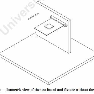
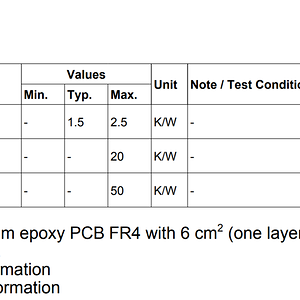
"Device on 40 mm x 40 mm x 1.5 mm epoxy PCB FR4 with 6 cm2 (one layer, 70 µm thick) copper area for drain connection. PCB is vertical in still air."
I know JEDEC (JESD51-2A) gives some guidelines about how to characterize devices but it is always in horizontal position. Not vertical.
What brings Infineon to do it vertically? if so, I have not found any information about the setup they used. Any suggestion?
Some bibliography:
Infineon Power Transistor Example
Cooling concepts for CanPAKTM package
Thermal Resistance - Theory and Practice
Gallery of Photos:
I am working on the estimation of Rth junction-TopCase for power transistors. For this purpose, I need the thermal information provided by the manufacturer. I mainly work with Infineon who always gives the same comment in their datasheets:
"Device on 40 mm x 40 mm x 1.5 mm epoxy PCB FR4 with 6 cm2 (one layer, 70 µm thick) copper area for drain connection. PCB is vertical in still air."
I know JEDEC (JESD51-2A) gives some guidelines about how to characterize devices but it is always in horizontal position. Not vertical.
What brings Infineon to do it vertically? if so, I have not found any information about the setup they used. Any suggestion?
Some bibliography:
Infineon Power Transistor Example
Cooling concepts for CanPAKTM package
Thermal Resistance - Theory and Practice
Gallery of Photos: