Continue to Site

Welcome to EDAboard.com

Welcome to our site! EDAboard.com is an international Electronics Discussion Forum focused on EDA software, circuits, schematics, books, theory, papers, asic, pld, 8051, DSP, Network, RF, Analog Design, PCB, Service Manuals... and a whole lot more! To participate you need to register. Registration is free. Click here to register now.

Rotary capacitor physics and design

Status
Not open for further replies.
Hi so my goal is to make a rotary capacitor, the purpose is rather complicated ...

I doubt your 'purpose' could be any more complicated than this thread itself. It would be useful to have some insight into what you're actually trying to achieve.
 

Hi,

Did I calculate correctly?

Xc = 1/ (2 × Pi x f x C) => 0.4 milliOhms
Each single millilvolt causes 2.5A of current.

How do you expect the wiring to be that low impedance?

Klaus
 

Returning from a journey, I see that the layered capacitance calculation fault this thread is based on still hasn't been corrected.

You have accepted that at rotating capacitor needs a certain spacing or air gap, no matter if the capacitor plate(s) are covered with additional dielectric layer(s) or not. As you state in post #12
I'm thinking ideally the real airgap which would be the empty space between the rotating disc circumference and stationary plate + the dielectric layer so the gap between the dielectric layer and copper plate should be much less than 1mm, say 0.3mm

The total capacitance is the series connection of air and one or two solid state capacitors, unfortunately the total capacitance is smaller than each partial capacitance, because

1/Ctot = 1/C1 + 1/C2 + 1/C3

In case of high permittivity solid state dielectric, the air capacitor is effectively defining the total capacitance. A simple example using your numbers:

E=8.85e-12 [F/m] d=0.3e-3 [m] A = 0.8 [m²]

C = E*A/d = 23.6 nF
 

....i'm having an oscillator located on the rotating shaft so I thought I need to get it's output off somehow ...

You should consider magnetic coupling and also EM coupling. If the requirement of actual power transfer is not necessary, just the signal nature.

... large enough capacitance in order for the reactance to be low enough at the desired frequencies...starting from 1 Mhz I would need about 400 uF in order to be good and going higher in frequency the capacitance requirement decreases of course.

400uF @ 1Mhz --> 0.4 milliohm. Why would you need it to be so low unless you are wanting to do serious power transfer ? If so, anyhow the ESR is likely to be much higher, so having ever larger capacitance values doesn't give any benefits.
 

it would be a good idea if you expounded on what you're thinking
since it seems you do not have a circuit and are flailing around in the dark,
a block diagram and a description would help.
 

well i'm just trying to understand whether the rotary capacitor idea is logical or practical at all because if it's not then making block diagrams for something that doesn't work isn't much use.

yes I am thinking of pushing large current (power) through but if I can't get the reactance low enough or ESR then that idea is again dead. well in theory the ESR should be low because in the circumferential capacitor plates there are connections made everywhere, in other words the discs themselves are like uninterrupted wires so this shouldn't be a problem I think.

I think more about what FvM said that for any capacitor where there are two dielectrics between the plates the total dielectric constant is determined mostly by the dielectric with lesser constant so if I have a dielectric with K=1000 and another one where K=1 (air for example) then the total dielectric constant will be dominated by this lower dielectric, is this right ?


PS. Maybe just an idea I could use ferrofluid, it would be easily kept in place by small magnets, there would be no air then as both plates would be touched by the fluid and I wonder how high the dielectric constant of such fluid could be if I made the fluid with high constant material particles in it like Barium titanate or other?
 

Hi,

For me speaking:
* idea
* specifications
* (hand drawn) block diagram
comes first

And in my eyes a hand drawn block diagram takes less time than 27 posts in a thread, but gives more information than a lot of words...

I'm still in the dark about your overall idea.

Klaus
 

Hi so my goal is to make a rotary capacitor, the purpose is rather complicated so right now i'm just looking whether I can make the capacitor at all with the intended capacitance.

you are missing the point of several of the last few posts

if you share what else is in your head about this gadget, not just the rotating capacitor,
more, better useful information may be provided.

a sketch of a few boxes labeled with functions, one high level function per box, with a few interconnects
will help one or another of us to help you

as an analogy, you keep talking about the tires without talking about the car
so how about a few boxes, such as motor, drive train, steering, wheels,
etc and some idea of interconnects?

complicated is not a problem
obscure is
 

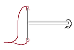
capacitor.png

I tried to keep this thread simple, pardon for failing to do that , I am not the best when it comes to explaining what I think.
It is just a rotating capacitor that has different capacitances at different points around the circumference of the disc, I couple this with an inductor and I get a variable frequency oscillator that I can control both with rpm of the rotor shaft as well as in other ways.


But as I already said, the key point here is the rotary capacitor part, without it the whole idea is garbage.
I think FvM already said a rather good point about the fact that a necessary airgap makes the capacitor of very low capacitance because with two different types of dielectrics present , the one with the lower constant will dominate the capacitance correct?


and then there was my question about maybe making a capacitor and have the dielectric with ferrofluid , it could be easily kept in place using magnets and I could in theory disperse say barium titanate particles in it or some other high dielectric constant particles to make it a good dielectric, with such fluid I could also move the plates closer together and there would be no air inside the gap between the plates?
what do you think?
 

I'm not aware of a liquid dielectric with sufficient high permittivity to serve your purpose. You can safely forget about this option.
 

Hi,

I still don't get the whole idea.
Why that big capacitance, why that low impedance, why that high RPM...

If the capacitance rotates .... the oscillator will give modulated frequency ... not (necessarily) modulated voltage or amplitude.
So what is all this good for?

Klaus
 

you are missing the point of several of the last few posts

if you share what else is in your head about this gadget, not just the rotating capacitor,
more, better useful information may be provided.

a sketch of a few boxes labeled with functions, one high level function per box, with a few interconnects
will help one or another of us to help you

as an analogy, you keep talking about the tires without talking about the car
so how about a few boxes, such as motor, drive train, steering, wheels,
etc and some idea of interconnects?

complicated is not a problem
obscure is

you are still missing the point
you aren't building a rotating capacitor to have a rotating capacitor
what will it be used in?
to accomplish what?
what voltage, current, power, frequency, etc etc ?

your thoughts about this capacitor have been delivered reasonably well
now you need to talk about the larger picture
 

this random thought project is getting really boring really fast now. Time to close this thread as a useless thread. It's just annoying everyone..... PLEASE !!
 

Status
Not open for further replies.

Similar threads

Part and Inventory Search

Welcome to EDABoard.com

Sponsor

Back
Top