Continue to Site

Welcome to EDAboard.com

Welcome to our site! EDAboard.com is an international Electronics Discussion Forum focused on EDA software, circuits, schematics, books, theory, papers, asic, pld, 8051, DSP, Network, RF, Analog Design, PCB, Service Manuals... and a whole lot more! To participate you need to register. Registration is free. Click here to register now.

Reverse sawtooth generator schematic needed with discrete components

Status
Not open for further replies.
Yes, it is getting a little confusing. :-? The circuit in #34 is includes my modifications to iimagine"s circuit to solve a couple problems I noted and added the output buffer. Note that I also changed some resistor values which seemed to improve circuit performance and increase the output voltage with a 12V supply.

Ok I will try this today and let you know.
 

I have just tested it. Unfortunately your circuit outputs a perfect...sinewave. No reverse sawtooth at all.

I have also tested again the circuit in post #30 but varying the vcc voltage. The output waveform is attached but it is very voltage depended (clipped tops above 3.7v). Also there is clipping bottoms below 6v. Above 6v bottom clips dissappear but the top clips are huge. The picture shows the test at 3.7v showing bottom clipping.
I have taken the output from the capacitor pin that connects to the resistor. I have also used 2n2222 and 2n2907 for the transistors.

It seems very linear otherwise. Any ideas of how to cope with the problems mentioned above?

UPDATE: I noticed when I touch my finger at the connection point of D4 and D5 the bottom clipping dissapears.
 

Attachments

  • 333.jpg
    333.jpg
    35.6 KB · Views: 87
Last edited:

Those deviations between the simulation and the actual circuits seem to be too great to account for by normal component variations so I have no good idea what the problem might be expect incorrect parts or incorrectly connected parts. :?:

Could you post a picture of the "sinewave" output?
 

I have just tested it. Unfortunately your circuit outputs a perfect...sinewave. No reverse sawtooth at all.

I have also tested again the circuit in post #30 but varying the vcc voltage. The output waveform is attached but it is very voltage depended (clipped tops above 3.7v). Also there is clipping bottoms below 6v. Above 6v bottom clips dissappear but the top clips are huge. The picture shows the test at 3.7v showing bottom clipping.
I have taken the output from the capacitor pin that connects to the resistor. I have also used 2n2222 and 2n2907 for the transistors.

It seems very linear otherwise. Any ideas of how to cope with the problems mentioned above?

I really do not see anything wrong with both circuits, if you have used the same components as drawn then they should work. At this point, I dont know what to tell you, but to double check your wiring and your scope settings. I also suggest that you assemble the original circuit posted by the author to check against my conversion. A pic of your prototype would also help us to see whats going on
 

Ok I have spotted the problem. It may have to do with different quality capacitors. Trying different caps gives a good waveform
The pictures shows the waveform plus all three circuits I have built.

Since the vcc must be between 3-5v for the circuit to operate correctly, how can I amplify this voltage?
 

Attachments

  • 444.jpg
    444.jpg
    36.1 KB · Views: 84
Last edited:

I would not amplifying this voltage yet, the main problem needs to be solved. I will have to investigate this and get back to you.
 

I do not believe that I did such a mistake. I was measuring in AC mode instead of DC. When switching to DC mode the waveform in circuit in post #17 is excellent and it's shape is independent of the voltage and it is current amplified. I think this is the most stable circuit so far.

The other two circuits, one of them is unstable in different voltages ant the other one continues to give a sinewave.

I am very satisfied by #17 performance!
 

I do not believe that I did such a mistake. I was measuring in AC mode instead of DC. ...................................

I am very satisfied by #17 performance!
That's a common mistake but you usually don't do it more than a couple times before you recognize the problem. It's best to leave the oscilloscope in the DC mode unless measuring AC signals with a significant DC offset.

Glad one of the circuits is working well for you.:)
 

As long as you are satisfied, all is good

I still do not understand why my converted circuit has limitation and why crutschow's version didnt work
 

As long as you are satisfied, all is good

I still do not understand why my converted circuit has limitation and why crutschow's version didnt work

I do not know, I have built the actual thing and tested it on scope (on DC also).
On the internet there are a few positive ramp generators but not negative linear ones. It is very interesting we have come up with a discrete circuit that works satisfactorily here (and current amplified).
The first use will be on a very poor man's spectrum analyzer. The inverse sawtooth will be used both to trigger the scope as well as to drive a varicap of the SA oscillator.
It will also be used in my transformer gates experiments, as a better generator than the one currently used.
**broken link removed**

Thank you all for helping!
 

Hello again,
Let's focus on circuit in post #17.
Assuming that it drives a varicap of a VCO, is there any way to add SPAN and CENTER FREQUENCY controls to it?

I can imagine the span control, as a function of controlling the varicap, like this: A portion of the falling edge of the linear ramp is only fed to the varicap, instead of the whole falling edge.
I can see the center frequency, as a function of controlling the varicap, like this: This portion of the linear ramp can be varied, either selecting more towards the top of the falling edge of the waveform or the bottom of the falling edge of the waveform.

I may be wring in my last two statements, please notify me if so.

Is this the kind of waveform you want to fed to the varicap?
 

Attachments

  • SPAN.PNG
    SPAN.PNG
    36.4 KB · Views: 92

Is this the kind of waveform you want to fed to the varicap?
It does not need to have the spaces between sawtooths. Just a reverse sawtooth continuous, like it is generated in post #17.

Shall I draw a diagram to let you understand better which portions of the waveform I am talking about?
 

Hello again,
Let's focus on circuit in post #17.
Assuming that it drives a varicap of a VCO, is there any way to add SPAN and CENTER FREQUENCY controls to it?

I can imagine the span control, as a function of controlling the varicap, like this: A portion of the falling edge of the linear ramp is only fed to the varicap, instead of the whole falling edge.
I can see the center frequency, as a function of controlling the varicap, like this: This portion of the linear ramp can be varied, either selecting more towards the top of the falling edge of the waveform or the bottom of the falling edge of the waveform.

I may be wring in my last two statements, please notify me if so.
I don't see any easy way to do that with just the sawtooth circuit. You could add an op amp buffer/attenuator to control the voltage swing (span) of the circuit. For center frequency control you could AC couple the signal and then add a variable DC bias.

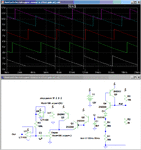
That circuit is shown below, added to the sawtooth generator. It uses a dual high-speed rail-rail op amp. The plot shows the reduced amplitude sawtooth (Uspan = 20% amplitude) for various settings of the Center Frequency bias pot (Ucf).

Sawtooth Inverted.gif
 
  • Like
Reactions: neazoi

    neazoi

    Points: 2
    Helpful Answer Positive Rating
I can imagine the span control, as a function of controlling the varicap, like this: A portion of the falling edge of the linear ramp is only fed to the varicap, instead of the whole falling edge.
I can see the center frequency, as a function of controlling the varicap, like this: This portion of the linear ramp can be varied, either selecting more towards the top of the falling edge of the waveform or the bottom of the falling edge of the waveform.

I am trying to think of the system (ramp generator/VCO) as a whole. Yesterday I did some experiments and I was able to sweep my VCO **broken link removed** at low speeds using a varicap in series with a capacitor and all this in parallel with the variable capacitor.
By altering the ramp generator capacitor, I altered the frequency sweep. This is how fast the signals in the spectrum analyzer are scanned.
By altering the series varicap in the vco, I altered the range (Fmin/Fmax). This is how much the ramp generator affects the vco at a given sweep speed.

According to this page https://www.radio-electronics.com/info/t_and_m/spectrum_analyser/spectrum_analyzer.php instead of using center frequency and span, one could use variable Fmin/Fmax to do the same job that could be done using center frequency and span controls. So I think the simplest thing here is to be able to alter the range of the vco. This means two things:

1. Altering the vco "start" frequency.
2. Altering the vco swing.

The first can be implemented using the vco's variable capacitor, or better by not using a variable capacitor at all and use just the switched coils.
The second can be implemented using a variable or switched capacitor in series with the varicap, or easier, I could use a variable voltage divider (potentiometer) at the sweeper output. This will divide down the maximum and minimum voltage of the ramp generator, i.e. the swing of the vco.
These two controls will interact with eachother in a way, but I believe this won't be a problem to focus on a certain signal by sequentially varying these controls.

The result is that the ramp generator does not need to be modified.
What do you think of it?
 
Last edited:

I am trying to think of the system (ramp generator/VCO) as a whole. Yesterday I did some experiments and I was able to sweep my VCO **broken link removed** at low speeds using a varicap in series with a capacitor and all this in parallel with the variable capacitor.
By altering the ramp generator capacitor, I altered the frequency sweep. This is how fast the signals in the spectrum analyzer are scanned.
By altering the series varicap in the vco, I altered the range (Fmin/Fmax). This is how much the ramp generator affects the vco at a given sweep speed.

According to this page https://www.radio-electronics.com/info/t_and_m/spectrum_analyser/spectrum_analyzer.php instead of using center frequency and span, one could use variable Fmin/Fmax to do the same job that could be done using center frequency and span controls. So I think the simplest thing here is to be able to alter the range of the vco. This means two things:

1. Altering the vco "start" frequency.
2. Altering the vco swing.

The first can be implemented using the vco's variable capacitor, or better by not using a variable capacitor at all and use just the switched coils.
The second can be implemented using a variable or switched capacitor in series with the varicap, or easier, I could use a variable voltage divider (potentiometer) at the sweeper output. This will divide down the maximum and minimum voltage of the ramp generator, i.e. the swing of the vco.
These two controls will interact with eachother in a way, but I believe this won't be a problem to focus on a certain signal by sequentially varying these controls.

The result is that the ramp generator does not need to be modified.
What do you think of it?
That sounds more complicated than varying the sweep amplitude and offset.
 

I don't see any easy way to do that with just the sawtooth circuit. You could add an op amp buffer/attenuator to control the voltage swing (span) of the circuit. For center frequency control you could AC couple the signal and then add a variable DC bias.

That circuit is shown below, added to the sawtooth generator. It uses a dual high-speed rail-rail op amp. The plot shows the reduced amplitude sawtooth (Uspan = 20% amplitude) for various settings of the Center Frequency bias pot (Ucf).

View attachment 99313

Hello,
I have drawn a diagram to help me undertand how the proposed circuit works, what is it's effect.
The waveforms have the same span setting but the offset (delay?) has been changed in the second one.
The third waveform is the actual output voltage at the buffer output (is it?) with the same span and delayed, like in the second one.

Have I understood that correctly?
 

Attachments

  • Untitled.png
    Untitled.png
    25.4 KB · Views: 77
Last edited:

Status
Not open for further replies.

Similar threads

Part and Inventory Search

Welcome to EDABoard.com

Sponsor

Back
Top