Continue to Site

Welcome to EDAboard.com

Welcome to our site! EDAboard.com is an international Electronics Discussion Forum focused on EDA software, circuits, schematics, books, theory, papers, asic, pld, 8051, DSP, Network, RF, Analog Design, PCB, Service Manuals... and a whole lot more! To participate you need to register. Registration is free. Click here to register now.

reverse phasing protection for mosfets in inverter circuits.

Status
Not open for further replies.
Does this mean i should use mosfets without internal diodes instead of IRFP 250 ?
Every power MOSFET has built-in reverse diodes, you don't get them without it. They are not necessarily shown in the symbol. It's a side effect of the transistor geometry that can't be removed on purpose.
 

As mentioned earlier that there are smart mosfets available that trips itself in case
of over temperature occuring. In my case mosfets simply burn ,so i think selecting
such mosfets will be one of the best options of reaching to a complete solution.
 

Disconnencting primary will be more feasible. Even if you are not charging, it is the same phenmenon when feeding voltages to primary accidently.
 

Disconnencting primary will be more feasible. Even if you are not charging, it is the same phenmenon when feeding voltages to primary accidently.

Than again the question arises .....How to sense the sense the accidental voltage on the primary(fast)and take the result to disconnect the primary (fast) so that no damage is done to the mosfets ???
 

You must protect all thyristers and mosfet channels by a series inductor to lower the dV/dT as well as dI/dT in power sources .
These transients are responsible for all breakdowns .
 

A proper rating fast blow fuse can work.
 
  • Like
Reactions: FvM

    FvM

    Points: 2
    Helpful Answer Positive Rating
A proper rating fast blow fuse can work.

Mosfet works as the fastest fuse and blow immidetly. I think as PIN mentioned earlier......

Another way to achieve this is to connect zenediodes from drain to gate (and see what-if the MOSFET get its driving from anouther source and the gate voltage instead will be driven upwards by force due to these zenerdiodes). The intention here is that when the drain voltage of the MOSFET vill rise dangerously high, then these zenerdiodes start to conduct and will make the MOSFET in question to partly start to conduct. In so doing it will pass current from drain to source of the MOSFET and this leads to the high-voltage spike over the MOSFET:s drain-source to be limited
.
I think connecting Zeners is a better idea if both the drives ( should be complimentary always) characteristic can be maintained. Worth a try.
 

Mosfet works as the fastest fuse and blow immidetly. I think as PIN mentioned earlier......

You are talking about assumptions, not real knowledge. Others have explained, why an overcurrent failure would be a more likely assumption. In this case, a fuse can help.

Zener diodes are suggested, if an overvoltage above the device ratings exists (it hasn't be shown yet, why it should) and the avalanche energy rating of the transistor is exceeded. Of course, a zener diode must have a lower breakdown voltage and considerably higher energy handling to be effective, which refers to a large TVS rather than a standard zener diode.
 

Mosfet works as the fastest fuse and blow immidetly
Mosfets can withstand over currents many times than its normal ratings for a small duration. Datasheet shows graph between time and maximum (pulse) current. Practically i found fuse to be effective beyond my suspectations. In an instant where sepeate wirings was not possible,a ups without over current safety available at the time was installed and provided a seperate socket for heavy loads. Planned to replace with another in a day or two and told the customer not to connect heavy loads like heaters and irons other than the socket provided.But the next day they connected an iron, found only fuse blown while trouble shooting. Gave a pack of fuses to customer and told him how to replace it and decided to the ups be there. During many months, there were four instances. Fuse always blew when accidently ups was overloaded , customer reported when he came to get another pack of five fuses.
 
Last edited:

Generally speaking, power MOSFETs can withstand over-current better than one can believe, but over-voltage is an instant killer
It is due to over voltage and not due to over current that my mosfets blow as discussed earlier.
In fact if i short my output (230V AC) terminals the inverter trips immideatly without any harm done and restart once the short is removed but once a different phase is applied at the output all MOFETS
blast with flames.
 

It is due to over voltage and not due to over current that my mosfets blow as discussed earlier.
Unfortunately, this assumption has neither been proved nor the concurrent explanations seriously checked.

I'm convinced, that there are several solutions to the problem by applying basic engineering knowledge.

Good luck with your projects!
 

When you short circuit output it detects overcurrent and drive to gates stops and hence output stops. Asumption is that, inverter is providing power to one phase (lighting load). The other phase already supplying power from another source is accidently connected to inverter output. If that is the case, even inveter outputis not enabled, current will flow and rectified by internal diodes of fets. When this voltage exceed battery voltage, a currrent starts flowing to the battery. As this current is in revese direction so overcurrent detector may or maynot activate. Even if inverter is disabled, current to battery is incresed as voltage of phase is increses. As battery is connected and it clamps to 24v this blows internal diodes as current increses manyfolds. Putting a circuit breaker in battery lead is also a option, it will diconnect battery. Althoug voltage is applied on primary, its current which destroy fets
 

Even if inverter is disabled, current to battery is incresed as voltage of phase is increses. As battery is connected and it clamps to 24v this blows internal diodes as current increses manyfolds

I think for my problem the above is the most satisfying answer of all as sometimes at some installations
mosfets blow during presence of mains when the gate drive is off now clearly indicating the internal diodes are the the main culprits in my case. Suggested improvement in this direction will lead to
the solution of my problem i.e reducing the fault rate of mosfets failures drastically to a very very low percentage.
 

A circuit breaker in battery lead is effective. 32A, 50A and 63A are common for 700 to 1500 watts. They also protect for fire hazard. A diode in series with battery can also serve the purpose.Double diode used in computer power supply are common.
**broken link removed**
checking battery current in reverse operating a relay lathed, can disconnect primary side from mains imediately.
 

i think MCB's will take some time before it trips so the using SBT 350 diodes seems a better solution.

i have modified the battery section circuit and attaching below for your refrance and further suggestions.

checking battery current in reverse operating a relay lathed, can disconnect primary side from mains imediately.

i have not fully understood the above can you elaborate .
 

Attachments

  • inverter2.pdf
    7.7 KB · Views: 115

Isn't SBT 350 only for 3 ampers. Here all the current drawn is passing through diode which may be around 60A. Speed is not an issue. Schottky diode is choosen only for low voltage dropout. In normal operation diode is forward biased. If a detector detects it reverse biased can also operate a relay to disconnect transformer primary from mains. If this protection also included, relay has to be remain in on position (latched) as when relay operates, diode is no longer reverse biased. The relay should not disabeled until manually reset. The diode is simple solution. It can be skipped by this circuit. The sense voltage then be from shunt resister which will be in reverse direction than normal.That's what i mean.
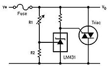
For over voltage protection as you suspect, the famous old crowbar circuit can be used. It reacts to overvoltage and blows the fuse.
Crowbar (circuit) - Wikipedia, the free encyclopedia

TRIAC Crowbar For AC Or DC Lines | Simple Circuit Diagram
43_1316794378.jpg


The diode is simple solution. It can be skipped by this circuit. The sense voltage then be from shunt resister which will be in reverse direction than normal.That's what i mean.

From your statement what i understand is that forward drop is not detected in reverse voltage at transformer primary(O/P) as current direction changes and for that reason you need to detect the reverse drop and provide your microprossesor or sensing ckt with extra information to disconnect the primary ( o/p) of transformer and Instead of using a diode , forward and reverse currents across the shunt can be used as under.

1) forward drop for normal Overload Protection
2) Reverse drop for accidental reverse voltage at tranformer Output.

Now my question is how to detect the reverse drop and forward drop from the same shunt that can be used as separate information for my processor as both being fault conditions ?
 

Its behavior is like ac signal. Adding offset to dc will enable sample +/- signal.

1) say negetive drop is -1V for reverse voltage (1St fault condition)
2) positive drop is +2v when overcurrent occurs.(2nd fault condition)

Now if i add 2 volt offset that means heathy condition will be from -1 + 2 = 1V and +2 + 2 = +4V
i.e 1 to 4 Volt . Below 1 is reverse fault and above 4 V will be Over current fault . Have i understood
correctly ?
 

Status
Not open for further replies.

Similar threads

Part and Inventory Search

Welcome to EDABoard.com

Sponsor

Back
Top