Continue to Site

Welcome to EDAboard.com

Welcome to our site! EDAboard.com is an international Electronics Discussion Forum focused on EDA software, circuits, schematics, books, theory, papers, asic, pld, 8051, DSP, Network, RF, Analog Design, PCB, Service Manuals... and a whole lot more! To participate you need to register. Registration is free. Click here to register now.

Removing Noise From Power Line

Status
Not open for further replies.
Yes, it is.
then what the purpose of bridge rectifier in your circuit?
is any PE or "earth" terminal on that AC/DC supply?
1_what should be the size of Y caps? My EMC filter has 2.2 nF, is it enough?

2_Is there any special type of cable for grounding or can i use regular ones?

1 it`s value is empirically defined
2 i think there is such special cables, but it`s application imho defined by mechanical or sertification requirements, not electrical
 
  • Like
Reactions: rhnrgn

    rhnrgn

    Points: 2
    Helpful Answer Positive Rating
then what the purpose of bridge rectifier in your circuit?
is any PE or "earth" terminal on that AC/DC supply?

I just want to protect circuit for reverse power connection because user has ability to reach power connection and sometimes they need to change power supply.

Yes we have Earth terminal in our power supply.

By the way, tomorrow i will finish my test and post results. I think the noise is differential and Y caps will remove noise.

I will also try to put a diode between 24V - 0V line. I know, it is not the same thing as flyback diode but i hope it will work =)
 

Connect 2nF Y capaciors to Shield = Not helped.

Choke = Not helped.

Diode between Only power poles of solenoid = removed noise totaly.

Diode between Only 24v DC supply's pole = Not helped.

What a testful day =)

I need a alternative way to remove noise without the diode which is between power poles of solenoid.
 

I need a alternative way to remove noise without the diode which is between power poles of solenoid.

you can replace the diode by RC-circuit. but why? it`s common practice to shunt relay winding by diode.

what is shield? did you try to connect y-caps to case?
try to increase its value to 20nF
 
  • Like
Reactions: rhnrgn

    rhnrgn

    Points: 2
    Helpful Answer Positive Rating
you can replace the diode by RC-circuit. but why? it`s common practice to shunt relay winding by diode.

what is shield? did you try to connect y-caps to case?
try to increase its value to 20nF

Because solenoid circuit is part of another machinery and circuit. I just want to increase my circuits durability and not sure whether can i add diode that circuit or not. Otherwise diode works great.

Shield = Earth ground. yeas i tried to connect y-caps but nothing changed or i didn't notice, there was still noise.

OK , tomorrow i will try to increase Y-caps.

Just because of that little solenoid, i will be a EMC master :D
 

Everything = not helped! Why dont you try a co-axial cable? It may help. I have seen many cases earlier when this has helped in preventing MCU trips, while driving chopper controlled DC motors.
 

Everything = not helped! Why dont you try a co-axial cable? It may help. I have seen many cases earlier when this has helped in preventing MCU trips, while driving chopper controlled DC motors.

We actually we have coaxial cable, i connected it to earth ground. i will go to factory next thursday we will see what happens. Thank You!
 

i went to factory and did some inspectations. There was a huge 3-fase motor. While it is turning there is a noise at 24V line at a frequency of 10 MHz and amplitude of 3 Volts.

Another point is that, they connect earth ground to notr phase at 3-phase stage. thats why there is no earth ground but notr =)

i told them to connect at least notr line to DC components earth ground inputs. Because they were not connected. My aim was to activate Y Capacitors.

After that day i learned that there is still resetting happens.

- - - Updated - - -

Now i am thinkin about remove that EMC filter and add toroid and choke. Do you have any ideas?

The important question, how can i select correct choke or toroid? is there anything else that help me to filter that DC line noise.
.
When i told my customer about earth ground, he told me "there are another computers and PLC's. there working fine just your electronic card has problems.". it was really embarrassing.
 

When i told my customer about earth ground, he told me "there are another computers and PLC's. there working fine just your electronic card has problems.". it was really embarrassing.
I believe he's true. The point is that PLCs and computers are designed to widthstand strong interferences. This is requiered by EMC rules and there are standarized tests to verify the correct operation in presence of severe noise, e.g. the burst test according to IEC61000-4-4.

In a noisy industrial enviroment, error free communication may be difficult, but at least the operation of the devices itself must not be affected. If this happens though, they aren't correctly designed. Wrong layout of the CPU board, insufficient supply filtering and protection of signal interfaces is the usual cause.
 

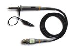
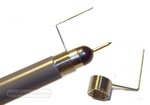
What is you noise measurement method?
probe.JPG
or
probe1.jpg
 

using second one gives more adequate results for high freq noise or high dv/dt signals.
try to measure directly on the out terminals of emi filter and then directly on vcc pins of mcu, then compare results and understand what choke to use.
as an idea, you can put into you device input filter shematic from PC ATX power supply :)
 
  • Like
Reactions: rhnrgn

    rhnrgn

    Points: 2
    Helpful Answer Positive Rating
one more important measurment. connect together signal and ground of oscilloscope. put that to different points of shematic:vcc and gnd of mcu, emi filter, etc. than measure this way noise when relay connecting/disconnecting. this measurment helps to separate noise from "noise, inducent to oscilloscope".
 
  • Like
Reactions: rhnrgn

    rhnrgn

    Points: 2
    Helpful Answer Positive Rating
This is my final situation =), it is looks like simple but i am thinking about sourcing my card with UPS :D. This message is copy-paste of another topic that i wrote. My aim is to inform you about my final situation.

Anyway,

The difference is source of noise is a solneoid valve, when de-activating it happens what happens and in my system. There is also a huge 330V AC motor and when motor rotates also there is noise at power line with approximately same characteristic. PLC and my electronic card sources from that power line. I can see motors noise at 24V stage too.

Is there any document which tells me how to decide whether is it a resonans problem or wrong filter issue?

Not1: Without RC filter which is between optocoupler and MCU, noise causes RESET MCU most often, after implementing RC filter there is still RESET but decreased alot but i need to remove that RESETting totaly.

Not2: Solneoid valves as you know, pumping the voltage(energy) to notr line when they are de-activated. On the other hand i am not sure about the characteristic of AC 3-phase motor =)

I will draw a schematic and ask an other question. I hope this will enlight you about my situation.

- - - Updated - - -

This is the Optocoupler and MCU part of the schematic:
https://obrazki.elektroda.pl/2953893300_1394693540.jpg

This is the power part of the MCU Power 24V in converted to 5V:
https://obrazki.elektroda.pl/4700688600_1394693542.png

This is the noise at MCU I/O when solenoid valve activated:
https://obrazki.elektroda.pl/2453973400_1394693534.jpg

Not1:Input of optocoupler is 24V.

Not2:Optocoupler works reverse. When you apply HIGH to input of optocoupler output is LOW. When LOW, output is HIGH.

Not3:There is also noise at output of power stage at 5V line but if i not connect PLC there is no reset occurs even if there is 5V at I/O pin. This shows me noise from power stage is not causes RESET.

Not4: When i connect PLC, MCU starts Resetting when that noise occurs.

Not5:Because of that reverse working, while plc is not sending any data, whether if PLC connected or not, there is 5V at I/O pin of MCU. This is also shows me noise from power stage is not only can causes RESET.

Not6:There may 2 reason:
1_Noise passes through optocoupler (i know it is very difficult, it is totaly isolated, and when i calculate CMR value it is around 500V/us it is more below CMR value of optocouplar which can handle).
2_There is noise at massage from PLC, there is also noise at 5V of MCU. Source of that noise is same , thats why frequency is approximately same but the way they reaches to I/O is different that is why there is a phase shift between them. When noise occur they may hop on them selves and increase voltage twice of noise, or increase the frequency of noise.

What an EMC problem is this, this is my first time. GOD pls dont push me that hard =)
 

Can you give a few details about the power and ground layout? E.g. four-layer board with continuous ground plane, double-layer etc. Or ultimately show a photo.
 

Can you give a few details about the power and ground layout? E.g. four-layer board with continuous ground plane, double-layer etc. Or ultimately show a photo.

Here it is. Protheus ares drawing =)
 

Attachments

  • LPS_Control_Card_v2.1.rar
    77.4 KB · Views: 84

Status
Not open for further replies.

Similar threads

Part and Inventory Search

Welcome to EDABoard.com

Sponsor

Back
Top