Continue to Site

Welcome to EDAboard.com

Welcome to our site! EDAboard.com is an international Electronics Discussion Forum focused on EDA software, circuits, schematics, books, theory, papers, asic, pld, 8051, DSP, Network, RF, Analog Design, PCB, Service Manuals... and a whole lot more! To participate you need to register. Registration is free. Click here to register now.

Remove AC hum from FM transmitter power supply

Status
Not open for further replies.
From an electrical grounding point of view, it would be ideal if the whole planet was made of superconducting material (cue Star Trek...) and everywhere had the same reference voltage to work against. However, that isn't even close to reality and the best we have is whatever is beneath our feet. Being kind to our planet, the moisture and dissolved conductive elements in the crust are reasonably good conductors, at least in most inhabitable places. The more contact area your house (or Tesla coil) earth has with the physical ground, the more likely it is to have good conductivity to elsewhere. The minimum depths for Earth connections are to maximize the likelyhood of a good connection.

You probably also have a wired connection from the AC outlet Earth pin to your nearest distribution transformer where it will be linked to neutral and also given a good connection to 'real planet' Earth rods. This is for electrical safety purposes and to allow safety devices (RCCB, ELCB etc) to operate but it does provide you with a reasonably clean ground reference.

Taking your Tesla coil as an example although the same principle applies to your transmitter, it generates high voltage between two places. If you didn't Earth one of them, it would be as 'live' as the other. You probably don't want high voltage arcs from the bottom of the coil, probably taking the easiest electrical route which would be through the coil primary and driver circuits!

Brian.

So this is the context of your comment about earthing the neutral, but I don't get it Brian.

And why is Earthing the neutral pin in a wall socket more of an electrocution risk than earthing the neutral pin at the street pole?

As was pointed out earthing either AC pin will result in shorting current to earth.

So why would anyone do that at any point in the distribution system?

And why is earthing the neutral of a wall socket more of an electrocution risk than earthing the neutral at the pole pig?
 
Last edited:

Hi,

On a wall outlet the neutral and live have fixed positions. It usually doesn´t change.
The same is true with a street pole.

But as soon as you connect the plug.. you can´t be sure which wire is neutral or live.
So if you try to earh the neutral.. but then turn the plug.. you will earth the live wire.

The problem in earthing neutral may also trigger the RCD to open the connection. --> no power anymore...

Klaus
 

Hi,

But as soon as you connect the plug.. you can´t be sure which wire is neutral or live.

Klaus

Huh? Don't understand. Its AC anyway so I am not even clear why there is this distinction in contacts anyway.

In AC schematics there never seems to be any such distinctions between the two side of the AC source.
 

Electrical safety is a complex issue and is discussed elsewhere on Edaforum.

Basically, in a domestic supply you have three wires, lets call them live, neutral and Earth. The names vary across languages and regions. The live and neutral are typically feeds from a three-phase distribution network after passing through a 'delta-wye' transformer. The transformer takes the three phases (no neutral or Earth) from the power generation plant and converts them to "TPN" (Three Phase and Neutral). At the same time the voltage is dropped from network voltage to your local supply voltage, typically 115V or 230V. For example, the local transformer here drops three phases at 11.5KV down to TPN at 230V. The Neutral wire goes to all the buildings in your local network, including your home. The three phases are also distributed around your local network but usually (different in some countries) only one of the phases goes to your property. In the UK, if we call the phases A,B and C, the first property would be wired to neutral and A, the second to neutral and B, the third to neutral and C and the fourth back to neutral and A and so on in sequence. This helps to balance the load on the transformer and although it never works perfectly, it cancels some of the current in the neutral wire as the sum of the phases is zero. If every property used an identical electrical load the current would theoretically cancel out and therefore so would voltage drop along the wire.

Now consider what would happen if ONLY the neutral and live wires went to your home. I'm not sure what your electrical supply voltage is but I'll assume for argument it is 230V. That means that across the live and neutral you have alternating 230V but not necessarily that one is zero and the other 230V relative to ground. They could for example be at 115V each or one could be at 200V and the other at 30V, in fact there is no reason why one couldn't be at 1000V and one at 1230V, they would still have the same voltage across the wires and equipment would see the voltage it needed. Everything would appear to be in order.

Consider now what would happen if a fault occurred in some equipment, lets say it has a power transformer in it and a short has developed between the primary and secondary sides or between primary and the iron core. The outlet side which you would assume to be safe could now be at high voltage, in fact up to or beyond the 1230V I gave in the example, but the equipment would still function normally. If someone, who could be several streets away but on the same distribution transformer had a fault or a current leak from live to the ground, it could tie their 230V to 0V and elevate the neutral on your socket to 230V at the same time. Clearly there is a safety issue both from excess voltages and from unexpected 'tilting' of the whole AC supply because of a current flowing somewhere else in the network.

The solution is to connect a third wire and keep it as close as possible to real 0V. We have to assume that the ground beneath our feet is as near to 0V Worldwide as it's ever possible to get. When such a reference voltage is available, it becomes possible to tie the neutral wire so it carries the lesser voltage of the two AC wires to your home. Linking the neutral and Earth distribution cables at the distribution transformer makes sure the neutral wires is as close to zero as possible and the live wire carries the 230V. The system isn't perfect but it is adequate. The neutral wire is not the same as the Earth wire though, they cannot be interchanged at individual properties and they should not normally be linked together again (exceptions apply in special circumstances). The neutral wire is carrying the main current from your home and then combines with neutral currents from other properties which could be on other phases, it can carry quite a complex current waveform. It also has some voltage dropped across it due to copper resistance, partly from current you draw yourself and later from the combined current of other properties. So although it may be 0V at the distribution transformer, it almost certainly isn't 0V by the time it is in use in your home. The Earth wire on the other hand doesn't carry load current so the voltage dropped along it under normal circumstances will be negligible. It CAN be used as a 0V reference although inevitably some 'nasties' creep in from leakage through things like mains filters. It is also safe to use multiple connections to real ground through rods or ground plates.

So in essence, Live should be the high voltage side of the AC supply, Neutral should be the low voltage side with the load current flowing between them. Earth should be as close to 0V as practical to achieve and can be used for safety shielding or detection of faults in the other wires.

Brian.

OK....I think I get the general gist of it.

So on the pole pig, I take it that the neutral of the primary coil is the one tied to earth for close as possible 0V reference?

It must be so.....if the secondary coil neutral was tided to earth then what is the difference if I tie my wall socket neutral to earth?
 

I'm not familiar with the term 'pig' (living next to a farm I do understand the animal description!) but I assume you mean a transformer up a pole.

Earth and neutral are only at the same voltage at the power source, the transformer. As soon as you move away from it, there will be a voltage drop in the copper resistance of the wires. You can check this easily by measuring the AC voltage between the Earth and neutral pins at your wall socket. Here I measure between about 2V and 6V depending on how much current is flowing along the cables. The Earth is the almost constant one, the neutral is the wire that rises and falls according to load.

If you tie Earth and Neutral together at the socket you negate the safety of having an Earth, in fact all you do is parallel the Earth and neutral wires back to the transformer and both will then have a voltage dropped across them relative to real Earth.


Brian.

Tesla coil enthusiasts call the transformers mounted on the street poles as 'pole pigs'. Some use these to power their spark gap tesla coils.
 

Most - if not all - domestic switch boards have an earth to neutral tie point, hence MEN system, Multiple Earth Neutral, the fact that they may be tied at the Tx or at other switchboards does not compromise safety - but rather enhances it.
 

None of the 100 or so in my village have linked N-E wires in the premises and some, including my own are new installations. The are multiple real Earths, I have two 1m copper rods at my own home but they are bonded to the Earth wire, not neutral. It was 'part-P' tested only a few weeks ago and passed, the only comment on the test certificate says high impedance back to the transformer but given the cable length there isn't much I can do about that.

My backup generator (in in a rural area where the power is unreliable) does have a bridge between N and E, emulating the transformer and ensuring the alternator output isn't floating.

Brian.
 

Hi,

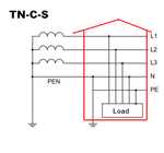
in TN-C-S systems it´s by far not unusal to connect the PEN at the house with an additional earth_gnd.
TN-C-S.PNG

Klaus
 

RE 3 phase electricity...

It also makes it possible to produce a rotating magnetic field in an electric motor

If each household gets 1 of the 3 phases then how is it that AC motors work with only one phase?????
 

how would the villagers know if the N-E link was installed on their fuse boards - modern ones are all covered.
 

RE 3 phase electricity...


If each household gets 1 of the 3 phases then how is it that AC motors work with only one phase?????

Because each phase also has a neutral. Neutral to any of the 3 phases is 230 volts. I'm not sure about phase to phase but I believe it's 415 volts. I live in the states and the transformers for homes is a center tap single phase. Neutral to either phase is 115 volts. Phase to phase is 230 volts. In either case you have alternating current, whether phase to neutral or phase to phase.
I've have also questioned how the neutral and ground could be connected in the service and still provide protection. This thread has cleared some things up but I'm still missing something. One other thing I might add is if you power a sub panel off the main panel the neutrals and grounds should be physically separated.
 

use 5V SMP and connect inductor at the input and output of the power supply to the FM transmitter and the Hum noise will disappear. meanwhile i hope you are not powering from a square wave source?
 

Status
Not open for further replies.

Part and Inventory Search

Welcome to EDABoard.com

Sponsor

Back
Top