Continue to Site

Welcome to EDAboard.com

Welcome to our site! EDAboard.com is an international Electronics Discussion Forum focused on EDA software, circuits, schematics, books, theory, papers, asic, pld, 8051, DSP, Network, RF, Analog Design, PCB, Service Manuals... and a whole lot more! To participate you need to register. Registration is free. Click here to register now.

Relationship between Q factor and the coupling factor of two wireless coils

Status
Not open for further replies.
For the selective filtering, as you already see in thread #48, the data link itself can reject some of the noise in the frequency at 13.56MHz. I guess this is not enough. If we look at this post answered by you (https://www.edaboard.com/threads/364923/#post1562652), I can see the noise coupling at the Rx data coil with both 6.78MHz power link and 13.56MHz power link.
In the mentioned thread there is no 13.56 MHz whatsoever.

----

For the selective filtering, as you already see in thread #48, the data link itself can reject some of the noise in the frequency at 13.56MHz. I guess this is not enough.
You guess it is not enough @36 dB of attenuation ? You do not have to guess, you have to calculate and see if it is good enough for you. (or measure as you did not measure even though you claimed to).

As a rough estimation, you can assume the current through the power coil is fairly sinusoidal and hence you have a linear circuit in which Superposition theorem can be applied, which means, you can estimate the influence on the data coil by the power coil at ~13.56 MHz with 36 dB attenuation. Estimate how much does that influence your data coil and if it distorts the 1 to 5 MHz data coil signal.

- - - Updated - - -

My power coils (both Tx and Rx) are 760308103307 from Wurth.
In the datasheet, there seems to be 2 different coils called wpc (wireless power coil ?) and nfc (non ferrite coil ? ). Do you actually have one of those? Which one ?
 

In the mentioned thread there is no 13.56 MHz whatsoever.

----


You guess it is not enough @36 dB of attenuation ? You do not have to guess, you have to calculate and see if it is good enough for you. (or measure as you did not measure even though you claimed to).

As a rough estimation, you can assume the current through the power coil is fairly sinusoidal and hence you have a linear circuit in which Superposition theorem can be applied, which means, you can estimate the influence on the data coil by the power coil at ~13.56 MHz with 36 dB attenuation. Estimate how much does that influence your data coil and if it distorts the 1 to 5 MHz data coil signal.

- - - Updated - - -


In the datasheet, there seems to be 2 different coils called wpc (wireless power coil ?) and nfc (non ferrite coil ? ). Do you actually have one of those? Which one ?

Hi CataM. Thank you! I am using 7.8uH inductor in https://katalog.we-online.de/pbs/datasheet/760308103307.pdf . Sorry for the confusion. I am not saying -36dB is not enough. In the mentioned thread there is only 6.78MHz noise. But when I used the 13.56 MHz power link, it is also observable noise in my data link. I expected a much clearner sine signal at the data link but no big difference in this data link sinusoidal signal was found. I am not sure if this is a measurement issue. If not, then I want to see if there is anything I can do in the circuits to make it clearner.
Regarding your method of the estimation, does that mean I need to probe the current in the power coil, and attenuate it by 36dB to see what will flow through data coil? Then use this estimated current to predict the noise voltage?
Thank you!
 

The mentioned inductor is the ferrite one. You can see its Q at high frequency...

I am not sure if this is a measurement issue. If not, then I want to see if there is anything I can do in the circuits to make it clearner.
Regarding your method of the estimation, does that mean I need to probe the current in the power coil, and attenuate it by 36dB to see what will flow through data coil? Then use this estimated current to predict the noise voltage?
No. I was referring to the fact that the influence of a 36 dB attenuated signal is relative to its strength... meaning that if the signal from the power coil is very very big and the signal from the data coil is low, it will have a big influence. If the signal of the power coil is not so "powerful", then, the data coil signal might be stronger and would have no visual influence (at least)... However, you are saying that it has influence.

In my opinion, regarding the fact that you are using a non-aired coil and its Q goes down at 13.56 MHz, I would stay at 6.78 MHz and use a band reject filter or other techniques (of shielding maybe ?).
 

The mentioned inductor is the ferrite one. You can see its Q at high frequency...


No. I was referring to the fact that the influence of a 36 dB attenuated signal is relative to its strength... meaning that if the signal from the power coil is very very big and the signal from the data coil is low, it will have a big influence. If the signal of the power coil is not so "powerful", then, the data coil signal might be stronger and would have no visual influence (at least)... However, you are saying that it has influence.

In my opinion, regarding the fact that you are using a non-aired coil and its Q goes down at 13.56 MHz, I would stay at 6.78 MHz and use a band reject filter or other techniques (of shielding maybe ?).

Thank you cataM. I do not know too much about the coil selection for the WPT design and want to ask some questions of the Q.
(1) Are you talking about "7.8uH coil has a high Q at 13.56MHz, so the signal of the power coil is very powerful. Therefore, the noise coupling is very strong from the power coil to data coil?"
(2) It seems the Q for the ferrite coil at 6.78MHz and 13.56MHz has no big difference. But actually I do find the interference from the power link is stronger at 13.56MHz than the case with 6.78MHz. The one I reported in another thread is acutually due to the measurement issue. If I probe touched the probe to the pads tightly, the interference from 6.78MHz is not so bad. Does this time domain observation make sense according to your theory?
(3) If I have to operate at 6.78MHz, do you have any suggestion to introduce the band reject filter? It seems I have asked you this question before, and there is no good way in a sharp rejection between 5MHz and 6.78MHz, is this correct? I have requested some shileding samples, but not have tried yet. I will let you know how it goes.
(4) If I still have the choice to change the power coil and let it operate at 13.56MHz, do you think changing the coil to wpc is a good choice? If that is still not a good choice, I can search for some other coils to build the 13.56MHz. Would you advise me what I need to pay attention in selecting the coils? For my case, there is no strigent requirement for the efficiency of the power link, as far as the noise coupling to the data link looks ok.
Thank you!
 

(1) Are you talking about "7.8uH coil has a high Q at 13.56MHz, so the signal of the power coil is very powerful. Therefore, the noise coupling is very strong from the power coil to data coil?"
No. The coil you are using is the bold line in the Q graph. It means you will have more power loss in the coil at 13 MHz which will raise the temperature of the coil and the core.

(2) It seems the Q for the ferrite coil at 6.78MHz and 13.56MHz has no big difference. But actually I do find the interference from the power link is stronger at 13.56MHz than the case with 6.78MHz. The one I reported in another thread is acutually due to the measurement issue. If I probe touched the probe to the pads tightly, the interference from 6.78MHz is not so bad. Does this time domain observation make sense according to your theory?
What? Q of the ferrite coil is drastically reduced. I can not even see in the graph the Q factor at 13 MHz for neither coil. In fact, neither coil should be used at 13 MHz because the inductance varies too much and hence detune the resonant circuits. Use 6.78 MHz or buy other coils suited for 13 MHz.

(3) If I have to operate at 6.78MHz, do you have any suggestion to introduce the band reject filter? It seems I have asked you this question before, and there is no good way in a sharp rejection between 5MHz and 6.78MHz, is this correct? I have requested some shileding samples, but not have tried yet. I will let you know how it goes.
You will have to design and see the reject filter how good (or bad) works between 5 MHz and ~7 MHz (to have some tolerance).

(4) If I still have the choice to change the power coil and let it operate at 13.56MHz, do you think changing the coil to wpc is a good choice? If that is still not a good choice, I can search for some other coils to build the 13.56MHz. Would you advise me what I need to pay attention in selecting the coils? For my case, there is no strigent requirement for the efficiency of the power link, as far as the noise coupling to the data link looks ok.
In my opinion your coils should not operate at 13.56 MHz. Even having suitable coils for 13 MHz you will have interference. Interference is caused by the coupling. You would have to look for coils with smaller geometry than the actual ones in order to have less coupling and of course, to have good Q at that frequency.
You should take into account that the reject filter does not prevent from picking up noise from the power coil, the shielding does. I do not know what you really want.

PS: You should talk with someone else if you want to choose a good shield.
 
  • Like
Reactions: bhl777

    bhl777

    Points: 2
    Helpful Answer Positive Rating
Hi FvM, thank you for your advise. My application is a biomedical circuits for implant purpose. Therefore, we have to use 6.78MHz or 13.56MHz power link.
For the selective filtering, as you already see in thread #48, the data link itself can reject some of the noise in the frequency at 13.56MHz. I guess this is not enough. If we look at this post answered by you (https://www.edaboard.com/threads/364923/#post1562652), I can see the noise coupling at the Rx data coil with both 6.78MHz power link and 13.56MHz power link. Do you have any suggestion how can I design extra filtering circuits in the data link to furthur reject the noise coupling from power link?
Thank you!

Hey BHL,
This problem is more easily solvable if all the requirements and characteristics are defined properly. I've honestly lost track on what you must accomplish in terms of power and data transfer, so it would help me greatly if you had a clear concise spec.

It must also include the dielectric medium and geometry of the both coils and the body dielectric effects. The group delay distortion and hence intersymbol interference ISI and carrier rejection must all be well defined limits and targets even if they are moving targets that effect your specs for min SNR and hence min BER.

All the bumps, ripple, loss and slope are easily explainable with accurate s parameter or impedance modeling of every part. The slope of of filters can be manipulated by ratios or formula according to defined band pass, band-reject and bandpass ripple or linear phase response. There are many tools to accomplish this. Friis losses are well known and the coil diameters must be larger than the separation for efficiency which affects coupling and impedance ratios. Inter-winding capacitance effects are well known as well as output impedance rise of Op Amps with f due to reduced gain at f. All sources of interference must be considered and identified for both emanation and susceptibility including lightning strokes and CB radios.

Can you share this? If you need to keep some info private, I understand. Is this for U of W or duplication of research, because they already have it working.

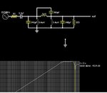
Here's a different simulation 1.jpg
 
Last edited:

No. The coil you are using is the bold line in the Q graph. It means you will have more power loss in the coil at 13 MHz which will raise the temperature of the coil and the core.


What? Q of the ferrite coil is drastically reduced. I can not even see in the graph the Q factor at 13 MHz for neither coil. In fact, neither coil should be used at 13 MHz because the inductance varies too much and hence detune the resonant circuits. Use 6.78 MHz or buy other coils suited for 13 MHz.


You will have to design and see the reject filter how good (or bad) works between 5 MHz and ~7 MHz (to have some tolerance).


In my opinion your coils should not operate at 13.56 MHz. Even having suitable coils for 13 MHz you will have interference. Interference is caused by the coupling. You would have to look for coils with smaller geometry than the actual ones in order to have less coupling and of course, to have good Q at that frequency.
You should take into account that the reject filter does not prevent from picking up noise from the power coil, the shielding does. I do not know what you really want.

PS: You should talk with someone else if you want to choose a good shield.

Hi CataM. Thank you so much! I will look into the shield solution. In my case, the noise coupling is more important than the power link design. Even if the power link is not efficient, it is still acceptable as far as it does not introduce extra noise coulping than the normal ones. I will let you know how the shield solution work.

Thank you!
 

Hey BHL,
This problem is more easily solvable if all the requirements and characteristics are defined properly. I've honestly lost track on what you must accomplish in terms of power and data transfer, so it would help me greatly if you had a clear concise spec.

It must also include the dielectric medium and geometry of the both coils and the body dielectric effects. The group delay distortion and hence intersymbol interference ISI and carrier rejection must all be well defined limits and targets even if they are moving targets that effect your specs for min SNR and hence min BER.

All the bumps, ripple, loss and slope are easily explainable with accurate s parameter or impedance modeling of every part. The slope of of filters can be manipulated by ratios or formula according to defined band pass, band-reject and bandpass ripple or linear phase response. There are many tools to accomplish this. Friis losses are well known and the coil diameters must be larger than the separation for efficiency which affects coupling and impedance ratios. Inter-winding capacitance effects are well known as well as output impedance rise of Op Amps with f due to reduced gain at f. All sources of interference must be considered and identified for both emanation and susceptibility including lightning strokes and CB radios.

Can you share this? If you need to keep some info private, I understand. Is this for U of W or duplication of research, because they already have it working.

Here's a different simulationView attachment 137347


Hi SunnySkyguy, I have one question of your design in this thread. You used a series connection 150pF cap between two 5.4uH inductance(which is the wireless coil inductance in my bench) to achieve a sharp attenuation between 5MHz to 13MHz. I am wondering is this sharp attenuation also achieveable for the case with wireless coils? This means we cannot have any connection between two inductors. Would you advise if it is possible, if we need to disconnect everything between the coils (except for that 1uH seires connected inductor, because I assum it is used for mimicking the coupling between two coils)?

Thank you!
 

Status
Not open for further replies.

Similar threads

Part and Inventory Search

Welcome to EDABoard.com

Sponsor

Back
Top