Continue to Site

Welcome to EDAboard.com

Welcome to our site! EDAboard.com is an international Electronics Discussion Forum focused on EDA software, circuits, schematics, books, theory, papers, asic, pld, 8051, DSP, Network, RF, Analog Design, PCB, Service Manuals... and a whole lot more! To participate you need to register. Registration is free. Click here to register now.

Realization of 22Hz transmitter by using magnetic coupling

Status
Not open for further replies.
hi dear users. please reply to my comment #99. I am waiting.


you have already been told once DONT be impatient and STOP making demands

doing that is really going to stop people helping you ... no one likes being demanded to do things, specially for those that wont help themselves


thanks to all for their valuable feedbacks. the proposed approaches by you dears pushed me into a meandering labyrinth and now I am completely baffled, because no schematic has presented for a better decision. but the most important note that I have noticed is that utilizing resonance inductive coupling method is almost useless due to absorption by a steel pipe. consider the following text:

1- please aware me if you think using the resonance inductive coupling is still a useful method.

2- since I have no previous experience in design of transceiver systems, plz help me step by step (accept my apologizes).

3-firstly I picked 22Hz frequency because some commercial PIG locator systems use that for passing steel pipe and soil. but which frequency is the best?

4-what is the best method for realizing this nightmare project?

best regards
Mohammad

1) possibly ... is that the way commercial systems do it ?

2) no one has the time or ability over the internet to help you step by step .... you need to find people close to you that can work directly with you in a well equipped workshop

3) well if commercial systems use that freq, then there will be a reason for that ..... probably cuz it's the best choice

4) buy a commercial system, as you apparently don't have the electronics knowledge to build one


Sorry to be blunt, but it's time you need to understand these things


regards
Dave
 
you have already been told once DONT be impatient and STOP making demands

doing that is really going to stop people helping you ... no one likes being demanded to do things, specially for those that wont help themselves


1) possibly ... is that the way commercial systems do it ?

2) no one has the time or ability over the internet to help you step by step .... you need to find people close to you that can work directly with you in a well equipped workshop

3) well if commercial systems use that freq, then there will be a reason for that ..... probably cuz it's the best choice

4) buy a commercial system, as you apparently don't have the electronics knowledge to build one


Sorry to be blunt, but it's time you need to understand these things


regards
Dave
please use words correctly! no one was demanded. it's only a help request. in here big men like Mr Brian, FvM,Betwixt and some others (now I cannot remember all) helped me and I owe to them forever. their valuable feedbacks will not be appreciated by words.
remember that due to variety of mentioned methods bafflement is inevitable!
here we are all friends and the smallest help will not be forgotten!
best regards
Mohammad
 
Last edited:

I think the acoustic method is more likely to succeed. It's how seismic events can be detected through the ground, all the way to stations at distances of thousands of miles.

Imagine, a slow-geared motor lifts a steel peg upward an inch or two above the pipe wall, then lets it go. The spring-loaded peg slams against the pipe. The sound travels through soil. Mount three mics, in contact with the soil. Calculate by triangulation to determine where the pig is.

The sound may reverberate inside the pipe, and thus emphasize some frequency. Tune your instruments to amplify that particular frequency.

As for the electromagnetic spectrum, it's true that photons of a certain wavelength can pass through objects. Example, X-rays but they don't go through rock or steel. I suppose it's too difficult (or too hazardous) to work with the rays that are at a frequency which is powerful enough to go through steel.

Someday we might discover how to invent scanners based on some subatomic particle, possibly different from photons. Example, neutrinos because they are not stopped by rock and steel.

- - - Updated - - -

We've heard of ground-penetrating radar. This is a possibility if it can go through pipe walls, and if your battery pack can has the necessary power to generate such waves.
[Edited to add: Perhaps ground-penetrating radar is along the lines of the original concept of this discussion? However it appears to be hypothetical instead of realistic.]
 

Ground penetrating radar generally only has a range of about 1.5 metres but the transmitting and receiving equipment are on the surface. That implies a range of 3m may be possible in a straight line. However, it will find but not penetrate solid objects, particularly metalic ones so even if it could trace the pipe location, it wouldn't find where the Pig was inside it.

A low power magnetic field generator at 22Hz would be difficult to pick up from 4m away in free air. Partially shielding it in soil will reduce the received strength and encasing it in metal pipe will virtually stop it completely, the combination of the two makes the concept of location just about impossible. As far as I can tell, the commercially available units have very short range, only a few cm and are usually clamped to the pipe or at least encircle it, making induced currents easier to detect.

The simple truth Dr Mohammad, is that none of us have any experience in this highly speciallized field so anything we suggest is based on theory and not on experience. We are doing our best to solve a difficult problem for you by suggesting alternatives you could try out but unless you can experiment to assess their feasibility, we can't tell which options are best to pursue.

So far we have suggested:
1. ways of inducing EM fields around the pipe
2. ways of inducing current into the pipe
3. permanent magnetic field sources
4. types of antenna and receiver with narrow beamwidth and high sensitivity
5. acoustic methods using mechanical generators
6. acoustic methods using electronic generators
7. acoustic triangulation
8. acoustic time domain reflectometry using 'ping' and multi-tone methods

Have you tried any of these methods and can you report back your results?

Brian.

hi Mr. Brian. thank you for your valuable presence.
Unfortunately Not. I should be assured that which one of the mentioned methods is 100% possible. as I investigated earlier, the acoustic method is used in under-sea pipelines and for underground pipelines the EM waves is commonplace. if I have a low-frequency EM transmitter the problem is solved, but I have not any method for realizing that.......do you have any idea or circuit for realizing 3Hz to 30 KHz transceiver?
 

I'm not entirely sure of your parameters - do you need a guaranteed position within a short distance over a range - or must you have precise distance permanently? I believe pipelines have regular break in points in case these things get stuck etc. - are you trying to define the distance between the break in points and location of the device to pull it out or detect exactly where it is in real time?
Are you the device operator and what design is the device - does it have a reliable rate of progress?

I can think of a few ways to implement this but you need to define the objective more precisely I think.
Distance shouldn't be an issue - I could suggest a solution there too maybe.
(Knowing precisely why the 5M range would help)

Size of budget would help if you need realtime along with exact pipeline parameters and some geology indications could be useful.

(Again as with betwixt and FvM not my field - it just so happens I've been researching some things you may be able to apply .... it's what I do....)

Precisely defining your situation would help immensely when asking these sorts of questions.
 

do you have any idea or circuit for realizing 3Hz to 30 KHz transceiver
You have to decide on transmitter frequency but I'm not convinced any particular frequency would be better than another.

For the receiver, you need the pick up coil (antenna) and a laptop with a microphone input. There are many audio analysis and spectrograph programs you can use. When a frequency, 22Hz or another, is decided upon, you can design narrow band filters to eliminate unwanted signals and then replace the laptop with a signal strength meter.

Brian.

design of receiver is almost straightforward. the major&critical problem is designing of extreme low frequency transmitter!
 

design of receiver is almost straightforward. the major&critical problem is designing of extreme low frequency transmitter!
I believe the transmitter design is straightforward, too. I sketched my ideas in post #51 two weeks ago.

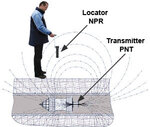
I also made a simple axisymmetric simulation setup to get an idea of the expectable field strengths and dependency on transmitter geometry, tube wall thickness and frequency. The transmitter orientation follows the previously manufacturer quoted literature.

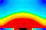
One result is that you need very wide simulation boundaries (e.g. several 10 m) for a quantitative results because the field is "conducted" along the tube. I wasn't able to implement ferromagnetic losses in the simulation, only eddy currents, thus I'm not sure if the tube field decays faster in reality. Due to tool restrictions, I'm, modeling the 0.5 m tube in a limited z=+/- 3m, r=4m volume. Wall thickness is 15 mm, µr=1000, conductivity 1.6e6 S/m.

The transmitter uses a 20 x 150 mm ferrite rod with a 100 mm cylindrical coil around it. With 1000 AW excitation at 22 Hz, I get about 10 nT flux 2m above the tube center. Due to the previously mentioned model limitations, this should be seen as an order of magnitude rather than an exact prediction.

Although I used a high µr power ferrite for the core, the simulation shows that lower µr values down to 500 or even 250 (usual antenna ferrite rods) reduce the field strength not more than 10 or 20 percent.

Transmitter_locator_use_en.jpg
Basic pig localization setup according to www.pigging.tools

tube pig.jpg
Field outside tube

tube2 pig.jpg
Field inside tube
 

I believe the transmitter design is straightforward, too. I sketched my ideas in post #51 two weeks ago.

I also made a simple axisymmetric simulation setup to get an idea of the expectable field strengths and dependency on transmitter geometry, tube wall thickness and frequency. The transmitter orientation follows the previously manufacturer quoted literature.

One result is that you need very wide simulation boundaries (e.g. several 10 m) for a quantitative results because the field is "conducted" along the tube. I wasn't able to implement ferromagnetic losses in the simulation, only eddy currents, thus I'm not sure if the tube field decays faster in reality. Due to tool restrictions, I'm, modeling the 0.5 m tube in a limited z=+/- 3m, r=4m volume. Wall thickness is 15 mm, µr=1000, conductivity 1.6e6 S/m.

The transmitter uses a 20 x 150 mm ferrite rod with a 100 mm cylindrical coil around it. With 1000 AW excitation at 22 Hz, I get about 10 nT flux 2m above the tube center. Due to the previously mentioned model limitations, this should be seen as an order of magnitude rather than an exact prediction.

Although I used a high µr power ferrite for the core, the simulation shows that lower µr values down to 500 or even 250 (usual antenna ferrite rods) reduce the field strength not more than 10 or 20 percent.

View attachment 134186
Basic pig localization setup according to www.pigging.tools

View attachment 134187
Field outside tube

View attachment 134188
Field inside tube

very impressive! God bless you.
is there another method for creating extreme low frequency EM waves?
 

Absorption is proportional to the primary intensity of the magnetic field; if you increase the effective magnetic field, they will be absorpbed proportionately more. Weaker radiation has a better chance of getting out.
 

Absorption is proportional to the primary intensity of the magnetic field; if you increase the effective magnetic field, they will be absorpbed proportionately more. Weaker radiation has a better chance of getting out.
Don't see how. Presuming linear behavior, which can be safely expected far below steel saturation field strength, both absorbed and transmitted signal is proportional to originally generated field strength. Increasing the generator field strength increases received signal.
 

Don't see how. Presuming linear behavior, which can be safely expected far below steel saturation field strength, both absorbed and transmitted signal is proportional to originally generated field strength. Increasing the generator field strength increases received signal.

I agree with you. another question that knocks my brain is : what's the best frequency for passing soil&steel pipe???
 

There is no optimal frequency. No frequency will work better than any other, the best you can do is avoid frequencies that are likely to be present in the vicinity. For example the magnetic fields around AC power wiring will be thousands of times stronger than the Pig signal so you need to avoid those. That more or less rules out any frequency around 50Hz or above. I imagine that is why 22Hz is used, it is far enough away from 50Hz to allow practical filtering and it avoids possible 'sub harmonic' and rectifier products at 25Hz and 30Hz. As lower frequencies are used, filtering becomes increasingly difficult and acoustic effects such as rumble from vehicle wheels and even flow through the pipe itself will start to mask or distort the signal you are looking for.

Brian.
 

I already stated that a few meters of soil with a usual range of electrical conductivity passes low frequency magnetic fields without noticeable attenuation.

Attenuation by a steel pipe is the relevant effect, it's caused by
- the ferromagnetic material acting as magnetic short
- eddy currents generated in the conductor

The 10 - 30 Hz range has obviously shown to be best suited for VLF pig detection. You'll see that reducing the frequency gives better penetration of the steel tube, on the other hand induced voltage in a receiver coil is frequency proportional and amplifier noise is increasing at lower frequencies,

thanks for your presence. I am going to finalize project and maybe the next week the fabrication my be implemented. while I was thinking two problem still remain vague:

1- is magnetic coupling (except acoustic and nuclear methods) the only way to realize it or can I realize ELF transceiver by another functional way???
2- In the magnetic coupling method, how to enhance the penetration ability of wave into steel pipe???

best regards, Mohammad
 

This idea is a possibility, not a certainty. Suppose you were to put a radioactive sample on board the pig, and detect it with a scintillation counter (extremely sensitive cousin of a geiger counter)?

I emphasize sample because my geiger counter has a radioactive sample taped to it, for testing purposes. (It isn't dangerous although you wouldn't want to store it under your bed.) Some types of smoke detectors contain a speck of Americium which is radioactive. Or a small rock of uranium ore (pitchblende) might be sufficient to place onboard the pig.

Scintillators are sensitive enough that they are used to detect radiation from a distance (example, cargo containers). Since lead shielding is needed to protect us from intense rays of this type of radioactivity, then perhaps it goes through steel? I have not used a scintillator so I can't be sure how well such a setup would work for you.

thanks, but due to health problems, the radioactive method is not proposed.
 

thanks, but due to health problems, the radioactive method is not proposed.

Very well, if it's a bad idea then it's a bad idea. We should be leery of being near anything radioactive. However do the rays need to be so intense as to jeopardize human health? I'm not certain. Perhaps it is safe as long as you follow established safety precautions. Your detector needs to be extremely sensitive, of course.
 

Status
Not open for further replies.

Part and Inventory Search

Welcome to EDABoard.com

Sponsor

Back
Top