Continue to Site

Welcome to EDAboard.com

Welcome to our site! EDAboard.com is an international Electronics Discussion Forum focused on EDA software, circuits, schematics, books, theory, papers, asic, pld, 8051, DSP, Network, RF, Analog Design, PCB, Service Manuals... and a whole lot more! To participate you need to register. Registration is free. Click here to register now.

radiated emission SEPPIC 24W

Status
Not open for further replies.

seridj_mse

Member level 2
Member level 2
Joined
Jan 18, 2021
Messages
53
Helped
0
Reputation
0
Reaction score
2
Trophy points
8
Activity points
311
HI,

We have tested our equipment SEPIC DC DC input:9-30V output : 12V/24W (PCB 2LAYER) for CISPR 16 radiated emission limits. The emission result is attached. I have trouble shooted the problem element.

for pics i know its about quartz 50Mhz but the probleme is with renonant , i tried with RC , and RDC snubber but i cant solve probleme


1663863275669.png
1663863302218.png
 

Hi,

you may optimize your schematic and PCB layout to reduce emissions.
We can´t help you with this, since we see neither one.

Just my wild guess: Optimize the layout and you don´t need external and expensive filters.

Klaus
 

Hi,

you may optimize your schematic and PCB layout to reduce emissions.
We can´t help you with this, since we see neither one.

Just my wild guess: Optimize the layout and you don´t need external and expensive filters.

Klaus
hi, thanks for ur reply , i will share shematic and layout but i think chnage pcb cost more than add filter ...
1663873890023.png


1663873842414.png

1663874286210.png
 
Last edited:

Hi,

in the PCB layout I miss (at least I don´t recognize) a clean concept for signal flow.
And I miss that every signal needs a return path.

I see a lot of big areas.
They are good if there is exactly the return path at the opposite layer - without cut, without detour.
Every detour means inductivity. Detour in the signal path as well as detour in the return path.

But big araes are not that good in the switching nodes with high dV/dt. Here the big areas create a lot of capacitive current, and noise in the GROUND side ... especially when there is no return path concept.
Here the nodes need to be as small in area as possible.

Big areas "may" reduce ohmic resistance, but not always. For your 2A you don´t need big areas to reduce loss as heating.
You need low impedance paths. HF impedance. This is important to reduce EMI.

****
If you are very experienced with HF style PCB design, then you can do 2 layer mixing with GND and signals. IF you are not that experienced, then just use the BOTTOM layer as uncut GND plane. Minimize the GND on th TOP layer.

Also the idea of having power input at one edge and the power output at the opposite edge of the PCB is more critical than
having | INPUT | GND | OUTPUT | close together. It avoids external GND loop problems because input and output refer to the same GND potential.

***

For sure your are free to use external filters and a metal case .... if you think this is cheaper than changing the placement of the components and traces on the PCB.
Unless you did not already produce high volume of PCBs .. I don´t understand where you expect the higher cost.

Klaus
 

Im not familiar with CISPR to answer specifically against that standard but i'd suggest most of your issues are conducted emissions radiating on the power input wires as you have no filtering. The radiated emission will probably change with length of cables also. I'd probably try adding a 40db @ 30Mhz filter to start with and see what happens to the radiated emission, the frequency is so high the filter will be pretty small and relatively cheap. I'd start with a small PI filter on the front end with something like 220nH & 22nF which should be quite effective at that frequency. Obviously once you've tried it the new data will show you its effectiveness

The other thing i notice is your layout has a lot of noisey Planes around the input and output nodes which will capacitively couple onto your wires possibly making your output filter less effective. i would also suggest something like a 10nF in parallel to the 10uF to aid the high frequency attenuation on your output filter.
--- Updated ---

It may also be worth trying some foil on the trop of your transformer and connect it to 0v, whilst its a screened transformer they have poor shielding.
 
Last edited:

Hi,

read my "If you are not that experienced..." recommendation of post #4.

Klaus

BTW:
* don´t put your answer within the "quoted text" (#1)
* don´t duplicate quote the same text (#2. #3)
* before pressing [Post reply] use the [Preview]

Klaus
 

Your report is at least incomplete. No chance to generate discrete 50 MHz harmonic series by the switcher. You have obviously other hardware in the test.
 

Im not familiar with CISPR to answer specifically against that standard but i'd suggest most of your issues are conducted emissions radiating on the power input wires as you have no filtering. The radiated emission will probably change with length of cables also. I'd probably try adding a 40db @ 30Mhz filter to start with and see what happens to the radiated emission, the frequency is so high the filter will be pretty small and relatively cheap. I'd start with a small PI filter on the front end with something like 220nH & 22nF which should be quite effective at that frequency. Obviously once you've tried it the new data will show you its effectiveness

The other thing i notice is your layout has a lot of noisey Planes around the input and output nodes which will capacitively couple onto your wires possibly making your output filter less effective. i would also suggest something like a 10nF in parallel to the 10uF to aid the high frequency attenuation on your output filter.
--- Updated ---

It may also be worth trying some foil on the trop of your transformer and connect it to 0v, whilst its a screened transformer they have poor shielding.
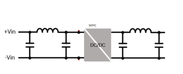
hi, thanks for this information , i tried with input and output PI filter with diffrent value (100n,10n,22n,1u,10u and 100uH,1uH,8uH and 12uH ) but nothing change , and what is stange is i didnt have problem with conducted emission ........

i tried with battery and short cable 4cm same result ...
Im not familiar with CISPR to answer specifically against that standard but i'd suggest most of your issues are conducted emissions radiating on the power input wires as you have no filtering. The radiated emission will probably change with length of cables also. I'd probably try adding a 40db @ 30Mhz filter to start with and see what happens to the radiated emission, the frequency is so high the filter will be pretty small and relatively cheap. I'd start with a small PI filter on the front end with something like 220nH & 22nF which should be quite effective at that frequency. Obviously once you've tried it the new data will show you its effectiveness

The other thing i notice is your layout has a lot of noisey Planes around the input and output nodes which will capacitively couple onto your wires possibly making your output filter less effective. i would also suggest something like a 10nF in parallel to the 10uF to aid the high frequency attenuation on your output filter.
--- Updated ---

It may also be worth trying some foil on the trop of your transformer and connect it to 0v, whilst its a screened transformer they have poor shielding.
--- Updated ---

Your report is at least incomplete. No chance to generate discrete 50 MHz harmonic series by the switcher. You have obviously other hardware in the test.
yes , i said 50mhz its about quartz , but i have same trace without harmonic if i test only SEPIC converter
 

My problem is that you don't report the actual test setup. Nor how you connected the filters.

I bet that schottky diode D1 is generating most of the interference power in the 60 to 130 MHz range. The existing bypass capacitors have apparently too much series inductance to ground to filter it effectively.
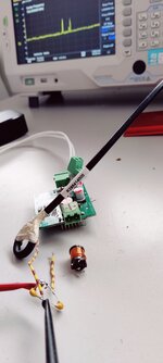
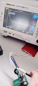
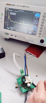
The test setup for the black screen its taked with spectrum analyzer with near field probe and the second pictures its from real test test in laboratory semi anechoic chamber .

for the filter u can see attach pictures

i cant undestand why the bypass capa have series inductance to ground ,however they are connected directely to areas (there is no piste ) ?


f6a_0.pngIMG_20220923_133135.jpg
--- Updated ---

My problem is that you don't report the actual test setup. Nor how you connected the filters.

I bet that schottky diode D1 is generating most of the interference power in the 60 to 130 MHz range. The existing bypass capacitors have apparently too much series inductance to ground to filter it effectively.

for diode schottky D1 , i tested with soldering diode so far from pcb and u can see result in pictures here


mesure cable diode.jpg


mesure self.jpg
 
Last edited by a moderator:

Thanks for clarifying the test setup.

Switcher emissions are expectable in the near field, direct board radiation in the frequency range of interest should be limited according to its size. Question is if they are able to propagate through the cables and be radiated.

Regarding series inductance, I wondered if the capacitor blocks share too few vias. But there's probably another issue. The fast commutation loop runs between C3-C6 and R6 diagonally through the ground plane, injecting common mode noise between in- and output ground terminals.

If I'm right, the emissions won't be reduced without revising switcher layout. Specifically single ended filters will still copy noise from the "hot" ground plane.
 

This is a classic newbie issue, ultrafast turn on of the mosfet slams the diode off, which diode makes just about all the noise seen in the 80 - 250MHz band, the ringing at turn off of the mosfet creates the lower frequency noise.

You should have included accurate waveforms of Vds and Diode k-a in the information - using a 250Mhz scope and probes rated for the same freq.

The only way around this issue is aggressive use of snubbers and slowing mosfet turn on - or put the whole thing in a metal box with careful i/o filtering, feed-thru caps etc ...
--- Updated ---


see this
 
Last edited:

This is a classic newbie issue, ultrafast turn on of the mosfet slams the diode off, which diode makes just about all the noise seen in the 80 - 250MHz band, the ringing at turn off of the mosfet creates the lower frequency noise.

You should have included accurate waveforms of Vds and Diode k-a in the information - using a 250Mhz scope and probes rated for the same freq.

The only way around this issue is aggressive use of snubbers and slowing mosfet turn on - or put the whole thing in a metal box with careful i/o filtering, feed-thru caps etc ...
--- Updated ---


see this

Hi, thanks for ur replay, in my case i dont think its a ultrafast on/off like in video , my Fsw its around 333.33khz .
now i dont have a fast scope , i will try to find one and i will share wavefroms vds.
 

that is amusing - you don't "think" the noise is due to fast turn on - but you have no stated idea about what is generating the noise ...
 

Hi,
my Fsw its around 333.33khz
It´s not this (fundamental) frequency that generatees the HF problem. It´s rather the "rise rate of the edges".

Or in other words:
Your 333.33kHz is not sinusoidal, thus it adds overtones. And the overtones create the HF problem.

Klaus
 

    seridj_mse

    Points: 2
    Helpful Answer Positive Rating
that is amusing - you don't "think" the noise is due to fast turn on - but you have no stated idea about what is generating the noise ...
i mean my switching frequency 333.33khz its not ultrafast like in video 1 Mhz, but yes maybe noise its due from it.
--- Updated ---

DIODE  MBRS3100T3G .png


i chnage ref of my diode from :

https://media.digikey.com/pdf/Data Sheets/Diodes PDFs/B320B-B360B_Rev10-2.pdf

to

https://docs.rs-online.com/a35b/0900766b80dac475.pdf

and the result pics of 450Mhz disappears.
 
Last edited:

Hi
The EMI peak is very sharp.
You drive Mosfet without manage/optimize turn on/ turn off time.
I suggest you reduce speed or rise time/ fall time off Mosfet by simply adding resitor from IC controller to Mosfet like 10Ohm. Yes, it will reduce EMI but also reduce little bit efficiency. Next, try to test with few kinds of Mosfet. Add RC snubber for input and output.
Lucky to you.
 

    seridj_mse

    Points: 2
    Helpful Answer Positive Rating
Hi
The EMI peak is very sharp.
You drive Mosfet without manage/optimize turn on/ turn off time.
I suggest you reduce speed or rise time/ fall time off Mosfet by simply adding resitor from IC controller to Mosfet like 10Ohm. Yes, it will reduce EMI but also reduce little bit efficiency. Next, try to test with few kinds of Mosfet. Add RC snubber for input and output.
Lucky to you.
HI, thanks for ur help , i will show the result of gate resistor and snubber 1nF/10ohms (1/4 w) in both mosfet and diode , with Input voltage 12v , when i increase it to 24v , the resistor starting to heat up (i should use 1W resistor or more ) and we have a pic again ....
 

Attachments

  • 10ohm.png
    10ohm.png
    29.4 KB · Views: 155
  • snuber.png
    snuber.png
    29.1 KB · Views: 158
  • j.png
    j.png
    27.6 KB · Views: 157
Last edited:

i should use 1W resistor or more
be aware that many power resistors are wire wound. This means high series inductance. Not suitable for (HF) snubber.

--> Be sure to use "low inductance" power resistors.

Klaus
 

    seridj_mse

    Points: 2
    Helpful Answer Positive Rating
Status
Not open for further replies.

Part and Inventory Search

Welcome to EDABoard.com

Sponsor

Back
Top