Continue to Site

Welcome to EDAboard.com

Welcome to our site! EDAboard.com is an international Electronics Discussion Forum focused on EDA software, circuits, schematics, books, theory, papers, asic, pld, 8051, DSP, Network, RF, Analog Design, PCB, Service Manuals... and a whole lot more! To participate you need to register. Registration is free. Click here to register now.

[SOLVED] Question regarding Transformers and there output voltage???

Status
Not open for further replies.

xpress_embedo

Advanced Member level 4
Joined
Jul 5, 2011
Messages
1,154
Helped
161
Reputation
396
Reaction score
189
Trophy points
1,353
Location
India
Activity points
10,591
Hello i just purchased a transformer from market having rating 12-0-12V and 2 A

After connecting it to a bridge and putting a big capacitor it is giving 17V DC Output.

I am not using any regulator.
Just a big capacitor of 4700uf.

Why 17V output is there when i am using a transformer of 12-0-12 Rating..
Anyone know why this happens.

Is there something related to Vrms and Vdc.

Pls help
 

The large capacitor charges to the peak of the rectified DC.

The peak of the rectified DC (unfiltered) = peak of the AC signal (amplitude) = (√2 * VRMS) = output DC voltage (filtered). Thus, in your case, the output voltage is (12V * √2) = 16.97V.

That's the 17V that you get.

Hope this helps.
Tahmid.
 
Thanks for the information
now I want to know what will happen if I connect a load which can take all two ampere current.

In this case my capacitors will not charge to peak.

So what is the voltage I will get after capacitors.
 

The capacitor will also try to charge to peak. Maybe when load is high, it won't be able to. So, output voltage might be a little less than expected. A rough estimation of the capacitance required to give full output voltage is: 1000uF/A (1000uF capacitance per ampere current). Since your capacitance is higher than that (by quite a bit) you will get peak voltage or near about that. Of course the transformer should be able to take the load and not have significant voltage drop under load.

Use a 2A load and see what happens.

Hope this helps.
Tahmid.
 

Ok I will implement it.
I am having 1 more question??
I had made a dual supply using this transformer.

But I need 12 volt and minus 12 volt to operate my circuit properly.

But I am getting 17 volt and minus 17 volt.
and due to this reason why circuit is not working properly

I cannot use regulators in my circuit I have not enough space on my pcb

is there anyway to drop the voltage down to 12 volt and minus 12 volt

with the help of zener diodes

please suggest me something to reduce the voltage without affecting my other circuits

and also without using the voltage regulator ic

thanks for your help
 

It's best you use regulator chips.

You can use resistor and zener to drop it down. But if you do that make sure that load is always connected and the output is not left open. You might burn the zener. This will be a big problem at 2A current. For small currents, though, there won't be much of a problem.
 

Hello Arun Sharma,

I cannot use regulators in my circuit I have not enough space on my pcb
You don't need Space on your PCB. The fix voltage regulator need a heatsink. So you can connect it with wires.

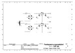
Do you really need 2A at -12V? Then look for the attached circuit.

Festspannungsnteil +-12V 2A.JPG

The negative voltage is also made with a positive fix voltage regulator, becaus negativ regulators are only aviable up to 1A.

Regards

Rainer
 

The negative voltage is also made with a positive fix voltage regulator, becaus negativ regulators are only aviable up to 1A.

I don't know of fixed voltage negative regulators, but there are quite a few adjustable negative variable regulators such as the LT1033. Of course the method you showed is a good alternative, making use of more common (and probably cheaper) positive voltage regulators.
 

Hello Tahmid,

negativ fix voltageregulators are aviable as 79Lxx with 100mA, 79Mxx with 500mA and 79xx with 1A from several manufactors. (xx means the regulated voltage, 5V, 8V, 12V and 24V.)

There are also circuits to increase the outputcurrent with an additional transsistor, but then you don't have a short circuit protection.

Regards

Rainer

Yes. I meant I didn't know of negative voltage regulators with current capacity > 1A. Sorry for the ambiguity.
 

Actually i am implementing this circuit..
Audio Amplifier
TDA.PNG

So i need dual supply +ve and -ve

With +17 and -17V, i am not able to get the proper audio from amplifier..
i give a 1Khz tone and measure the output on Oscilloscope, then i came to know some distortion in negative cycle.

After that i disconnect the supply and used DC Supplies (that are variable as well as costly) and connect then in order to obtain +ve and -ve supply.
When Supply in increased from +15V to -17V same thing happen
I am getting distortion in negative cycle.

So its sure that it is due to the supply i am having.

If somehow i will be managed to drop the voltage to less than 15V, it will be good for my amplifer.
I can't use Regulator's..
 

If somehow i will be managed to drop the voltage to less than 15V, it will be good for my amplifer.
I can't use Regulator's..


Is that due to space constraints? Or some other reason?

You could use a 9V transformer or a 10V transformer.

9V * √2 = 12.73V

10V * √2 = 14.14V
 

Actually i cannot change the transformer..

I have a to just do it without changing anything..

Is there any way with the resistors to drop the voltage.

By putting a simple resistor can be drop voltage going to tda2050 supply pins.

I think we can but have to consider the wattage of that..
 

By putting a simple resistor can be drop voltage going to tda2050 supply pins.

I think we can but have to consider the wattage of that..

Yes, but the drop across that resistor and thus output voltage will vary depending on output load. With low load, output voltage will be maximum. Output voltage will be lower when load is higher.

TDA2050 can withstand up to ±25V. Why are you trying to decrease voltage? Due to excessive noise? Did you use a volume control pot? Is there excessive noise/distortion even at low to medium volume? It is common to experience noise/distortion at high volumes near maximum volume.
 

negativ regulators are only aviable up to 1A
They are at least rare. You have LT1185 (-3A)

TDA2050 maximum supply voltage rating is +/-25V, it should easily work with +/-17 V.
 

Yes, but the drop across that resistor and thus output voltage will vary depending on output load. With low load, output voltage will be maximum. Output voltage will be lower when load is higher.

TDA2050 can withstand up to ±25V. Why are you trying to decrease voltage? Due to excessive noise? Did you use a volume control pot? Is there excessive noise/distortion even at low to medium volume? It is common to experience noise/distortion at high volumes near maximum volume.

yes you are right.
But I am getting distortion of after plus minus 15 volt

thats y decided to decrease supply to 15v


Although the voice is good but has something which irritates ears.
 

Is that at maximum volume, because you are almost always likely to be irritated when an amplifier plays at maximum volume. Use volume control and adjust it so that you play at lower than maximum volume. Test throughout the entire range and you're probably likely to hear the irritating noise at or near maximum volume.
 

Hello arunsharma0731, hello Tahmid,

I think the amplifier make an oscillation at high frequency. These IC's like to do it about the high amplification of 30dB.

The capacitors C3, C4, C5 and C6 must be as close as possible to the Pins of the IC. If not it can be oscillate.

Regards

Rainer
 

But I am getting distortion of after plus minus 15 volt
Unfortunately we can't see from a distance what's happening in your circuit. I presume, that you implemented the example circuit shown in your previous post and that no other circuit parts, e.g. preamplifiers generate the distortion. In this case, it may be either a defective amplifier IC or possibly a problem of instability caused by bad ground wirng or insufficient bypassing.
 
Thanks Everyone...

But i am not having distortion at +-15v and after that i am having that little bit distortion which is creating the audio unpleasant to listen..

My IC is not defective as i had made 5 such units and all are working same.. have distortion in the negative half cycle when seen on oscilloscope.

And the input is given from phone 3.5mm jack.
 

Status
Not open for further replies.

Part and Inventory Search

Welcome to EDABoard.com

Sponsor

Back
Top