Continue to Site

Welcome to EDAboard.com

Welcome to our site! EDAboard.com is an international Electronics Discussion Forum focused on EDA software, circuits, schematics, books, theory, papers, asic, pld, 8051, DSP, Network, RF, Analog Design, PCB, Service Manuals... and a whole lot more! To participate you need to register. Registration is free. Click here to register now.

Query about crossovers

Status
Not open for further replies.
The power transformer is center-tapped so its total voltage might be 89.2VAC. Then the DC voltages will be plus and minus 62VDC at full power and a little higher with reduced power.
To protect the speakers then keep the volume control turned down.

When my speakers burnt the volume wasn't high it was just a wire issue, keeping the volume don't can stop it from burning but if something should happen isn't there a circuit to protect the speakers.
 

Many power amplifiers have a circuit that detects DC on the output when something in the amplifier has failed, then it disconnects the speaker with a relay.
Distortion produced by an amplifier that is clipping or is playing loud acid rock noise can blow a delicate tweeter.
 

one of those circuits to disconnect speakers is what I am referring to. I was asking if you have any that I could build.


does this look like a working amplifier it has a pcb made for it also

- - - Updated - - -

I am assuming its 1000w into a 8ohm speaker
 

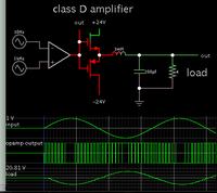
Here is a simple class D amplifier. It doesn't have as much power as your posted schematics, however it has less to go wrong. It could be a start for experimentation.


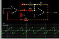
To get the sawtooth wave here is an example:


I suspect your speakers were unable to handle the power- it is good to use a bit oversize (overpower) speakers. Protection circuits cannot protect a speaker that is unable to handle the load.

does this look like a working amplifier it has a pcb made for it also

It may need 1.5kW to deliver 0.5kW output at the speakers! The 12 MOSFETs shall need massive heatsinking...
 

Here is a simple class D amplifier. It doesn't have as much power as your posted schematics, however it has less to go wrong. It could be a start for experimentation.


To get the sawtooth wave here is an example:


this looks simple are those Jfet? Can I use Mosfets?
How would I use the sawtooth schematic would it be added to the 1st schematic to the left of the opamp?

- - - Updated - - -

I suspect your speakers were unable to handle the power- it is good to use a bit oversize (overpower) speakers. Protection circuits cannot protect a speaker that is unable to handle the load.


It may need 1.5kW to deliver 0.5kW output at the speakers! The 12 MOSFETs shall need massive heatsinking...

you wouldnt recommend this amplifier then? regardless of that does it look functional?

- - - Updated - - -

this is simple to look at but it shows how young I am to this stuff, I need a little guidance, Ok I see 30hz at the non inverter side of the opamp but on a regular amplifier that would normally go to ground based on the amplifiers that I have seen. the inverting leg has 1khz which would normally be the positive not sure if this means the design can only allow those values maximum to enter or those are the minimum values but those 2 pins would be signal in rite?

also at the gate of the transistor it says out why is that, unless its a test point? also how much wattage would a circuit like this be able to deliver?
 

Can I use Mosfets?

Yes, mosfets or transistors.

How would I use the sawtooth schematic would it be added to the 1st schematic to the left of the opamp?

Yes. The sawtooth amplitude needs to be a little greater than your audio amplitude.

I see 30hz at the non inverter side of the opamp but on a regular amplifier that would normally go to ground based on the amplifiers that I have seen. the inverting leg has 1khz which would normally be the positive not sure if this means the design can only allow those values maximum to enter or those are the minimum values but those 2 pins would be signal in rite?

Sorry, it's too hard for me to follow. You ought to run your own simulation, matching your own preferences.

* The op amp needs a bipolar supply, so its output can go into both positive and negative polarity.

* Say your audio signal is line level (1V). The op amp applies gain (20 or 50 or 90x). Its output needs to reach the same voltage amplitude as you want at your speaker.

This is why it's best to start simple. The project requires a great deal of adjusting and experimentation.

it says out why is that, unless its a test point?

Yes, 'out' marks where the scope trace is tapped.

also how much wattage would a circuit like this be able to deliver?

Peak voltage can be as great as the supply. It's up to you to decide what voltage is your supply, and what resistance is your load. Those parameters determine your wattage.
 

Ok then also which simulator do you guys use

- - - Updated - - -

Yes, mosfets or transistors.


Sorry, it's too hard for me to follow. You ought to run your own simulation, matching your own preferences.

I see specific frequency ranges on the opamp I am just asking if those values are limits not to pass
 

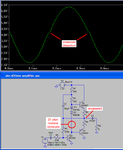
Many of us use the free simulation program called LTspiceIV from Linear Technology's website. You can draw a schematic on it and it has the spec's for some standard part numbers in its memory and many more parts online. It can show waveforms, distortion percentage and harmonics and frequency and phase responses. Here is a simple power amplifier on it showing some crossover distortion on its waveform:

I can't post it because MANAGE ATTACHMENTS DOESN'T WORK HERE ANYMORE!

- - - Updated - - -

Attachments work now:
 

Attachments

  • crossover distortion2.PNG
    crossover distortion2.PNG
    24.8 KB · Views: 96

Ok then also which simulator do you guys use

LTSpice is popular and free. Someone here can post a schematic for you to run on your computer, and vice versa.

My simple schematics are modified from Falstad's animated interactive simulator. In fact they are deceptively simple. Example, notice the op amps have no supply leads. And suppose you want +95 -95V supply? I don't know if any op amp can survive that. (The Legend-Stage, post #45, appears to do an op amp's function in the left half of the schematic, using discrete components which can tolerate 95V.)

Another problem is, the sawtooth oscillator (post #46) remains stagnant when I reset it. This means it might be unreliable to get it operating in a hardware version.

I see specific frequency ranges on the opamp I am just asking if those values are limits not to pass

Since you are talking about a sub-woofer, then this means low frequencies below 100 Hz. The carrier frequency needs to be many times that, although it need not be as high as the carrier you would use to amplify 15 kHz. You'll want to experiment to find out what frequency creates satisfactory sound, using the components available to you.
 

ok so these schematics that you sent here I realize they are in png format I installed lt spice but it seems to require an asc file format so im assuming this isnt the way to send a schematic to someone.

about the amplifier now I think I would try to do some proto typing to test this out. I have tl072 chips and I have irfz44n I only have 10uh inductors but once i can test it out on a bread board i would do some test runs to see what would happen

- - - Updated - - -

for what the opamp can survive in terms of voltage I would normally check that but when the circuit get more complexed then I start to wonder where some connection lead to

- - - Updated - - -

By the way does anyone know a good and simple vu meter than I can build, I want to build 1 tomorrow
 

ok so these schematics that you sent here I realize they are in png format I installed lt spice but it seems to require an asc file format

Yes, LTSpice file format has .asc extension. However this message board prefers to transfer files as .txt.
Therefore change .asc to .txt, then send it as an attachment.

When you get a file from this message board, change .txt to .asc. This turns it into an LTSpice format. Then you can load it directly into LTSpice.
 

Ok I am using windows 10 it doesnt show extension anymore like older windows so I will have to check how I can change the extension, did you see what I asked about Vu meter?
 

We post an ".asc" file only when we want to let others use the simulation. To make a copy of the schematic and graph to post it in a thread here I press the PrtScn (print screen) button and paste the schematic into Microsoft Paint program where I can make it have a fuzzy JPG file type or a very clear PNG file type.

I use an LM3915 IC driving 10 LEDs as a level meter. I use peak detection to see exact levels, not VU that shows only average levels.
 

VU meter discussion seems off-topic here. Don't broaden the original thread to a boundless "all about DIY audio" discussion.
 

Status
Not open for further replies.

Similar threads

Part and Inventory Search

Welcome to EDABoard.com

Sponsor

Back
Top