volker@muehlhaus
Advanced Member level 6

- Joined
- Apr 11, 2014
- Messages
- 3,348
- Helped
- 1,086
- Reputation
- 2,176
- Reaction score
- 1,166
- Trophy points
- 1,393
- Activity points
- 21,131
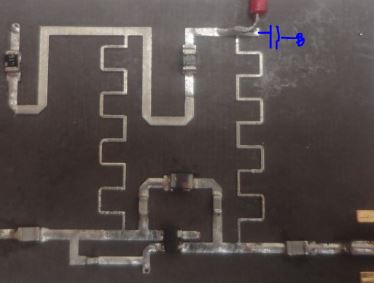
In your PCB, there is one obvious mistake: you do not have any capacitor to ground at the voltage supply lines (meander). Add something like 100pF to ground at the DC supply (if the meander lines are 1/4 wavelength lines: at the DC side of each meander).
Let me repeat this ... independent of your bias problem, your circuit (layout) is not complete. In simulation the 3V supply is an ideal short circuit for RF signals ... but in your hardware it is not. You really need to add a blocking capacitor.


