Continue to Site

Welcome to EDAboard.com

Welcome to our site! EDAboard.com is an international Electronics Discussion Forum focused on EDA software, circuits, schematics, books, theory, papers, asic, pld, 8051, DSP, Network, RF, Analog Design, PCB, Service Manuals... and a whole lot more! To participate you need to register. Registration is free. Click here to register now.

Programmer schematic for AT89c2051 on paralell port

Status
Not open for further replies.
at89c2051 prog pcb

Hi pkedvessy,

Set SPP mode in BIOS for parallel port.
In XP force WIN95 compatibility mode for program.
It should work. I test the harware in 5 different PC with different frequency.
If the byte of the first address is different from 02H then you've a problem.
 

    V

    Points: 2
    Helpful Answer Positive Rating
at89c51 programmer amazon

If I set up any compatibility mode, the software read out nothing, so I got 00FF 00FF 00FF 00FF...
And if I dont set up any compatibility mode, all the read out files will be different! But may be the same just slip the code anyway!

Added after 1 hours 12 minutes:

Is it a problem, that there is only 11,26V on the RST pin while the programming is running???

Added after 30 minutes:

I read the 89c2051 datasheet, and I read this: When the power is on, there must be 5V on the rst pin, and when the programming starts, there must be 12v!
But when I power on my device, there is 3,34V on the rst pin, and when I start the programming, ther is 11,26V. Is it normal???
 

at89c2051 programmer schematic

The voltage applied on RST pin at power up must be greater than 0,7Vcc, that is greater than 3,5v
You should get 4,2 - 4,3v (like with +12v, that drops to 11,3v). 11,3v on RST pin during programming will violate the specs but it still works for me.

Download the parallel port tester from here: http://www.xmediastudio.com/Download/PortTester.zip
and check the hardware as follows. At least you will know that your problems are due to the software and not from hardware.
It's really madness and a lot of peoples could claims it would be better to switch to another micro upload through ISP with the same program (I call AT89S52).
Well, it will not fit on the keyboard logger wires due to his size (DIP 40 or PLCC 44).
Nevertheless, if you can convert the assembler code from 8051 to your favorite AVR, then all the things bellow are useless.

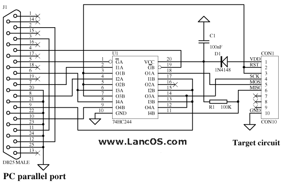
All pins are from DB25 plug.

1. Push C0 Pin 1 turn yellow
2. Push C1 Pin 14 turn yellow
3. Thus the RST pin voltage drops to 0v (insert now the micro in socket and aply the power supply)
4. Push D7 Pin 9 turn green
5. Thus data in the storage register of 4094 appears at the outputs.
6. Push D6 Pin 8 turn green (D6 is pushed in the first shift register)
7. Push D6 Pin 8 turn off
8. Repeat steps 6-7 five times more, for the next five '0' load into shift register
9. Push D5 Pin 7 turn green (set data '1')
10. Push D6 Pin 8 turn green (clock in) (P3.2 pin must be kept at high level)
11. Push D6 Pin 8 turn off
12. Push D5 Pin 7 turn off (set data '0') (the XTAL1 is at low level in order to reset the address counter of 89C2051)
13. Push D6 Pin 8 turn green (clock in)
14. Push D6 Pin 8 turn off
15. Push D4 Pin 6 turn green (set strobe, that is data in each shift register is transffered to the storage register
16. Push D4 Pin 6 turn off
17. Push C1 Pin 14 turn off (pin RST goes to +5v)

Now you must be able to see the low nibble of the first signature byte 1110
It will appear on the status register as follows:
S4 blue lit pin 13
S5 blue lit pin 12
S7 off pin 11 (pin 11 is hardware inverted, that's why appears off, even if is '1')
S6 off pin 10

18. Push C2 Pin 16 turn yellow (on the status register appears the high nibble of the first signature byte 0001

S4 off pin 13
S5 off pin 12
S7 blue lit pin 11 (pin 11 is hardware inverted, that's why appears lit, even if is '0')
S6 blue lit pin 10

19. Push C2 Pin 16 turn off
20. Push D6 Pin 8 turn green (D6 is pushed in the first shift register)
21. Push D6 Pin 8 turn off
22. Repeat steps 20-21 five times more, for the next five '0' load into shift register
23. Push D5 Pin 7 turn green (set data '1')
24. Push D6 Pin 8 turn green (clock in) (P3.2 pin must be kept at high level)
25. Push D6 Pin 8 turn off
26. Push D6 Pin 8 turn green (clock in) (the XTAL1 pin will raise to +5v after strobe)
27. Push D6 Pin 8 turn off
28. Push D5 Pin 7 turn off (reset data)
29. Push D4 Pin 6 turn green (set strobe, that is data in each shift register is transffered to the storage register
30. Push D4 Pin 6 turn off
31. Push D6 Pin 8 turn green (D6 is pushed in the first shift register)
32. Push D6 Pin 8 turn off
33. Repeat steps 31-32 five times more, for the next five '0' load into shift register
34. Push D5 Pin 7 turn green (set data '1')
35. Push D6 Pin 8 turn green (clock in) (P3.2 pin must be kept at high level)
36. Push D6 Pin 8 turn off
37. Push D5 Pin 7 turn off (set data '0') (the XTAL1 is at low level)
38. Push D6 Pin 8 turn green (clock in)
39. Push D6 Pin 8 turn off
40. Push D4 Pin 6 turn green (set strobe, that is data in each shift register is transffered to the storage register
41. Push D4 Pin 6 turn off

Now you must be able to see the low nibble of the second signature byte 0001
It will appear on the status register as follows:
S4 off pin 13
S5 off pin 12
S7 blue lit pin 11 (pin 11 is hardware inverted, that's why appears lit, even if is '0')
S6 blue lit pin 10

18. Push C2 Pin 16 turn yellow (on the status register appears the high nibble of the first signature byte 0010

S4 off pin 13
S5 off pin 12
S7 off pin 11 (pin 11 is hardware inverted, that's why appears off, even if is '1')
S6 off pin 10
 

at89c2051 программатор xp

After the 3 step, there should be 0V between the GND and the RST, but I have 4,5V! Is it normal?

Added after 4 minutes:

I replaced the BC239 to BC182 and the BC328 to BC212, because I can't buy this two part!
 

89c2051 programer

I found the problem, but I has a new :-(
I burn the chip, but at the 150h adress I got a verification error! After and before it, the code is the same with the file... Why is it?
 

atprog

Hi pkedvessy,

Probably, address 0150H could be a bad address on chip. Try with other chip if you've one.
I'm just curious, what was the problem revealed after you replaced the BC239 to BC182 and the BC328 to BC212 ?

Regards,
silvio
 

atmel 89c2051 programmer

jacor said:
h**p://www.pjrc.com/tech/8051/aicp-schematic.html

That's the old story with the chicken and the hen.
If my choise would be such kind of programmer I would try this approach:
**broken link removed**
The programmers pins could be isolated with CD4066 gates (like in w*w.prjc.com) in order to get the ICSP feature, beyond of our first purpose to program the flash.

BTW, can someone explained why on earth would someone strive enough to program in the circuit 89C2051 (i mean without removing from the target board) rather than using one with ICSP provided by default and with more than 2K flash memory ?

Oh, almost I forgot. Atmel has just released the new 89LP series.
The AT89LP family consists of devices with 2 to 64 Kbytes of in-system programmable Flash memory, and is available in a variety of pin options, from 14, 20, 28 and 44. They include on-chip DataFlash®, 10-bit ADC, analog comparator, pulse width modulators, programmable watchdog timer, enhanced UART, internal RC oscillator.
First member of this series is AT89LP2052 with 20MIPS throughput at 20Mhz and ISP features. More is coming.
http://www.atmel.com/dyn/resources/prod_documents/doc3547.pdf


Regards,
silvio
 

dl2tm programer

hi

i build a dl2tm and it is not working ok
when i burn some bin file with icprog 105d its ok buth when i read that its not the same for example first line is Dim I as byte
but when i read that from chip it write Dok i ad bylt
and whole program is like that only the last line is ok
i tray program with bascom demo but it say error while write byte
but when i read is same problem
i cant program with ATprog_2 but i can read and is the same
problem
i tray with some other programs but problem is same
which type in bios should i chose now is spp i hawe spp epp ecp


can anyone help please ?

:?:
 

at89lp2052 programmer

Hi Josip,

You should try the ecp setting for parallel port.
What operation system did you use now ?

As far as I know dl2tm is supported by Bascom.
I'm not so familiar with basic, but what is the binary value for "first line is Dim I as byte" which you wrote with icprog and what is the one read back ?
 

at89c2051 programmable timer schematic

y u want to build this programmer? If it's for knowledge purpose then it's ok, but if otherwise u think of saving money, that won't be of any use, better buy one. that would be a much better option.

Regards
 

89c2051 simple programmer

hi
I use win XP pro with SP2 and win ME
and with both I have the same problem
I will try ecp

"first line is Dim I as byte" is not a basic comand it is just example
first line in program which I burn is : " Dim I as byte "
but when I read it back from chip it is not the same its something like:" Dok I ad blty "
and hex code is diferent for example I burn this :
066 03d 069
but when I read it back from chip it is :
064 03f 069
I noticed that hex go 2 numbers up or down
but I dont know why

thanks for help

by :cry:
 

at89c2051 parallel programmer

Hi Josip,

Did you set corectly the icprog to work in win xp ?
I mean the ICprog NT/2000 driver (icprog.sys), compatibility mode for Win2k,
and enable NT/2000 driver in Options / Misc ?
 

programator atprog 4.0

Hi Silvio
yes i did that but its the same problem
i dont no what to do i buy a new microcontroler but it is same
i tray with some other programs but its same problem


:|
 

firmware of sunrom 89 series programmer

Hi Josip,

Sorry to hear that but believe me if you get stuck you better choose another way.
If the parallel port is an issue for you and still insist to use At80C2051 then you have two options:
1. buy a ready made programmer for AT89C2051
2. program the AT89C2051 through serial PC com port. In order to do that switch a while to AT89S52 which is ISP programmable
Program the "hen" AT89S52 with the code **broken link removed**
According to **broken link removed** you can then program your "chicken" AT89C2051.
Obvious the master "hen" is AT89S52 that replaces the AT89C2051 from figure 1 **broken link removed**.
You're using now the serial PC communication which shouldn't give you headaches compared with parallel port, regardless the OS and CPU clock speed.

But since AT89S52 is programmable through parallel port too, it's recommended to use a proven reliable software on parallel PC port.
Thus, download ponyprog software from http://www.lancos.com/e2p/V2_06/ponyprogV206f.zip
Then build two interfaces
at89s.gif

and
avrisp-siprog.gif

and stick it together
 

isp pro at89c2051

Hi

thanks for help
I tray everything but problem is same i will tray build new programmer
what you think about tafe programer ?
 

how to burn at89c2051

josip said:
what you think about tafe programer ?

I never tried the TAFE programmer.

dt206act.gif


But if you want to play then read first the Peter Averill's page:
https://www.dontronics.com/dt206.html
and
https://www.dontronics.com/pa_pgm.html where you can download the Peter's software **broken link removed**
As you can read the readme.txt file inside the zip file:

The original prototype programmer was constructed on vero board.
I have tested it on a 486 66MHz and a Pentium 100MHz both work OK.
The latest programmer that I am using is the PCB layout provided. I
am using it on the same computers as mentioned above. This layout
has how been built by many other people and tested on a variety of
computers.


Remember the last Peter's update was done at 3-8-98.

It's true that since the release of IC-Prog 1.05 claims an improved TAFE Programmer speed and starting with IC-Prog 1.05D a fixed timing bug in all LPT based Programmers (including the DL2TM and TAFE)

A small excerpt form Peter's page:

Operation with Peter Averill's software.
There are a few things to be aware of.

The Calibration program is designed to be used with Peter's original power supply design which has a system of pots to set the voltages accurately, however we have found that off the shelf resistors allow for reasonably accurate settings and the voltages can be checked prior to programming a Micro, by measuring the voltages at pin 1 of your programming socket. The program allows for 12Volt and 5Volts, but not 0 volts, so don't be concerned if you don't see pin 1 go to zero during the calibration phase. These voltages should be +/- 5%. Resistors R2, R2, and R4 determine the voltages.

The programmer works with both a uni-directional (one way communication) or bi-directional (two way communication) printer ports, however there are some limitations with uni-directional ports.

If you can't set up a bi-directional printer port, you can do what is called a blind program, that is, there is no verify, or ability to read the contents of the AT89C2051 Micro.


Hope you don't want to get into much trouble than you are now.

It's true that Peter uses the Calibration program in order to perform a fine tuning on +12 V programming voltage by measuring the voltage at pin 1 of AT89C2051 socket according with proper values of R2, R3 and R4.
I said that looking at the DL2TM programmer at the input of U3 7805 where D3 looks like never exists (the main power supply is +12v)
Second the D1 placed at Q2 collector is useless and can be removed, this way we can raise the voltage of pin 1 of AT89C2051 for a suitable programming voltage (keeping the same voltage on Q2 emmitor)
The D1 could be used if the +12v rail falls, but when that happens, the +5v goes off too, thus useless protection.

Well I don't want to bother you with all these.

As you can probably noticed, there a lot of peoples having trouble with timings on parallel port and different CPU clocks and operation systems.

If you want to try the TAFE programmer and not work then:

1. Buy a ready made programmer for AT89C2051
2. Switch to another microcontroller (with ISP features if possible)
3. Try to program the AT89C2051 through serial COM port (the "hen" timings are nearest to the specs than ones got on parallel port)

Here is another programmer for AT89C2051 (among others) done through serial COM port with "hen and the chicken"
**broken link removed**

The firmware for the "hen" : https://www.sunrom.com/index.php?main_page=redirect&action=media&goto=25
 

89c2051 prog buy

Hi
thanks for link Silvio
I will will build Atmel 89 Series Device Programmer or Easy downloader v1.1

I will see but i think it will be Atmel 89 Series Device Programmer it is better
solution
do you have any experiance with that programmer ?
 

programer for 89c2051

Hi Josip,

There a lot of positive comments on this forum regarding the Atmel 89 Series Device Programmer from Sunrom.
I can't joined them since I didn't purchased the programmer nor buid it.

The easy downloader v1.1 is working but as you said the one from Sunrom covers a large range of microcontrollers.
I don't see any reason for which it will not work for you. So go for it.

You only need to get a master programmed with the firmware downloaded from sunrom.

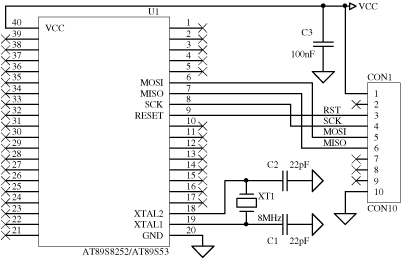
If you get an AT89S8252 or AT89S53 then you can use the ponyprog software to do the job.

If you have an AT89S52 then you can program it with this software :

**broken link removed**

If you keep the parallel cable shorts you can even try this one:

**broken link removed**

As you can see the programmer sold by sunrom it's on same site :

**broken link removed**
 

Status
Not open for further replies.

Similar threads

Part and Inventory Search

Welcome to EDABoard.com

Sponsor

Back
Top