Continue to Site

Welcome to EDAboard.com

Welcome to our site! EDAboard.com is an international Electronics Discussion Forum focused on EDA software, circuits, schematics, books, theory, papers, asic, pld, 8051, DSP, Network, RF, Analog Design, PCB, Service Manuals... and a whole lot more! To participate you need to register. Registration is free. Click here to register now.

problem with MOSFET number

Status
Not open for further replies.

PVM137

Newbie level 4
Newbie level 4
Joined
Jan 22, 2017
Messages
5
Helped
0
Reputation
0
Reaction score
0
Trophy points
1
Activity points
43
Hi
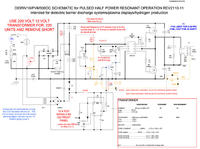
in this schematic the Q1 & Q2 are P&N channel MOSFET.
but Q1="1RFP450" and Q2="IRFP450"
I can't find any datasheet about "1RFP450"
Is there any alternative to this two MOSFET's ??


That schematic looks wrong, check the data sheet for the IR2153 driver, I don't think it can produce an inverted drive signal for a P-channel MOSFET. I suspect they are both supposed to be IRFP450.

Brian.
 
  • Like
Reactions: PVM137

    PVM137

    Points: 2
    Helpful Answer Positive Rating
But in another schematic also Emphasis on "1RFP450"
It doesn't Typographical mistakes.


Where did you find these schematics?
Often one web site copies images from another and the mistake is repeated. As far as I can tell, the IR2153 is a standard bootstrapped totem-pole driver so both MOSFETs should be of the same type. The top one OR the bottom one should be turned on (with dead time) but not both at the same time. Inverting one and using a P-channel device, if it worked at all, would turn them on at the same time.

Brian.
 
  • Like
Reactions: PVM137

    PVM137

    Points: 2
    Helpful Answer Positive Rating
Often one web site copies images from another and the mistake is repeated. As far as I can tell, the IR2153 is a standard bootstrapped totem-pole driver so both MOSFETs should be of the same type. The top one OR the bottom one should be turned on (with dead time) but not both at the same time. Inverting one and using a P-channel device, if it worked at all, would turn them on at the same time.
OK.

Where did you find these schematics?
This is the schematic of a plasma generator named PVM500 that it's manufactory plain in the website for customers to download & instructions. and i'm want to test it.
this circuit produce up to 40 kv peak to peak with frequency adjustable 20-60 KHz.


Thanks for any help or any data about this type of circuit.
 
Last edited:

IRF450 is 500 V MOSFET in TO3 package, IRFP450 a similar chip in TO247. Obviously high- and low-side transistors are NMOS type.

IR2153 is self-oscillating driver with complementary outputs and can work in this circuit.
 
  • Like
Reactions: PVM137

    PVM137

    Points: 2
    Helpful Answer Positive Rating
Status
Not open for further replies.

Part and Inventory Search

Welcome to EDABoard.com

Sponsor

Back
Top