Continue to Site

Welcome to EDAboard.com

Welcome to our site! EDAboard.com is an international Electronics Discussion Forum focused on EDA software, circuits, schematics, books, theory, papers, asic, pld, 8051, DSP, Network, RF, Analog Design, PCB, Service Manuals... and a whole lot more! To participate you need to register. Registration is free. Click here to register now.

Preamplifier circuit design

Status
Not open for further replies.
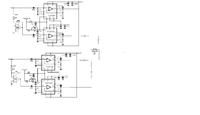
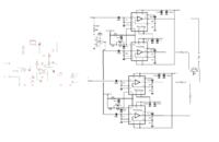
Are you sure that schamatic is correct Audioguru? You appear to have a double inversion on the lower amplifier so both outputs would be in phase.

Brian.
 

So with a 50-0-50v Dc supply into 8 ohms with this circuit I could get 115w for a mono set up all I would need to do is pair this with a similar circuit for the left and right to get a stereo setup.

How would I parallel more of those Tda7294 together.


Thanks for pointing out my horrible mistake, Brian. Here is the corrected version:

- - - Updated - - -

So with a 50-0-50v Dc supply into 8 ohms with this circuit I could get 115w for a mono set up
No, the ICs will get too hot and will shut down if you turn up the volume. The datasheet shows the bridged amplifiers producing 115W into 8 ohms with fairly low distortion when the supply is +/-25V.
To make +/- 25V the transformer should be 18V-0-18V. The preamp does not need a separate transformer and rectifiers, its voltage regulator can be fed from the +25V.

The efficiency is about 50% so at 100W output the heating is 50W in each IC. The IC turns off when its chip temperature reaches 145 degrees C and its thermal resistance is 1.5 degrees C per Watt. A huge heatsink might have a thermal resistance of 1 degree per Watt. The ambient might be 40 degrees C. Then the chip will be at 145 degrees C when the heating power (and output power) is (145 - 40)/(1.5 + 1)= 42W so you might need a fan.

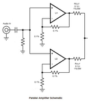
Amplifiers can be paralleled for bridged amplifiers to drive a 4 ohm speaker. Add an accurate 0.1 ohm 1% tolerance 3W resistor in series with the output of each amplifier and use 1% tolerance resistors to set their gain.

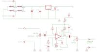
Your preamp schematic is very confusing since you show the symbol for a single opamp with all the pins of a dual opamp. Show two separate opamp symbols instead.
 

Attachments

  • corrected bridged amplifiers.png
    corrected bridged amplifiers.png
    53.3 KB · Views: 113
  • preamp.png
    preamp.png
    27.2 KB · Views: 119
  • parallel amplifiers.png
    parallel amplifiers.png
    39.2 KB · Views: 113

Ok here is the modification.


- - - Updated - - -

whats your thoughts on that circuit.

- - - Updated - - -

trying to parallel the circuit, so in this set up I would still use it as mono, is this the correct method?


I've never been happy about parallel amplifiers but the output is basically correct. The input side is more complicated than it needs to be, you can connect Vi to the 470nF capacitors on the top and third IC in your schematic and the output of just one op-amp to the capacitors feeding the second and last ICs. Note that to get more power out you also have to drop the loudspeaker impedance to 4 Ohms, if you keep it at 8 Ohms the power will be the same as before.

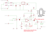
Your pre-amp stage is OK but it will have poor low frequency response. It will fall to half volume at about 31Hz which is probably higher than you want. The limitation is C1 and POT2 (the volume control) which together form a high pass filter. I suggest increasing the capacitor to 10uF or increasing the volume control to 47K or both. Make sure the input pin to the 12V regulator has a capacitor to it's ground pin and it is physically located close to the regulator. I suggest 10uF.

Brian.
 

sorry for bad sketch Its my first time trying to use paint and im at work also.

input of 12v reg is a 10uf cap and resistors going to speaker is 0.1ohm 3W

with a setup like this whats the maximum voltage I could use as my supply and how much watt would I get out at 4ohm and 8 ohms respectively.


update for the schematic
 

The absolute maximum voltage for the TDA7294 is +50V and -50V (100V total) although it isn't recommended that you use more than +40V and -40V.

The power you can get is about 150W to an 8 Ohm loudspeaker from a single bridged pair and theoretically twice that if you double up the amplifiers but in reality, you wouldn't get anything like that. The problem with parallel amplifiers is matching them exactly and that's difficult. You might think of it as fitting two car engines in one car body and linking them with a strong chain. If they work exactly the same, you get twice the engine power but if there is any difference, the more powerful one wastes energy to drag the other along with it. Using a 4 Ohm load is OK if both amplifiers drive it equally but you might overload one or the other if they don't do half the work each.

Warning: Be careful, most 12V voltage regulators are not rated for input voltages higher than 35V so wiring directly to +Vs may exceed it's rating.

Brian.
 

The datasheet of the TDA7274 by ST Micro is very confusing. They say the "peak" output power is 180W when the supply is 80V, the distortion is 10% and the speaker is 4 ohms but the power dissipation (heating) is hardly manageable. They say "a generally used average output power value is one tenth of the maximum output power at T.H.D.=10 %" which I disagree with since if an amplifier plays a crescendo longer than their brief peak power timing then it overheats and turns off. How will you keep the average power low enough? Why would anyone play sounds at horrible 10% clipping distortion?

Then ST Micro shows a bridged amplifier producing 100W at the beginning of clipping, 110W when clipping distortion is fairly low and 150W when clipping distortion is horrible at 10% but with a supply that is only 50V and a 8 ohm speaker. I calculated that at an output of 100W then both ICs will become very hot and might turn off.

Enzy, you mentioned Mono. You need a stereo to mono mixer circuit (a couple of resistors) and if it is a subwoofer then it needs a lowpass filter circuit and the mids and highs stereo amplifiers need matching highpass filter circuits.
 

In this case i would use an external cross over so I wouldn't use an internal low pass or high pass filter. Based on what the drawing is showing now it's mono correct? So I can use it for bass.
 

An external crossover for a subwoofer uses a big expensive inductor that wastes amplifier power. An active filter circuit feeding the power amplifier is best.
Isn't the source playing stereo? Then you need a simple stereo to mono adapter that can simply be 2 resistors.

The datasheet of the TDA7294 amp IC shows when 2 are bridged an output of 170 Whats (with horrible clipping distortion) into 16 ohms with a +-35V supply or 110 Watts with fairly low distortion. When the two amplifiers have additional amplifiers in parallel with 0.1 ohm balancing resistors then the output will be about 200 Watts into 8 ohms. The ICs will become very hot so a good heatsink must be used and maybe a fan.
 

I was refering to a active cross over not a passive cross over.


So this circuit would work just fine.
 

An active crossover circuit is a lowpass filter for the subwoofer and matching highpass filters for the stereo mids and highs.
The resistor value of only 1k in your stereo to mono converter might overload the output of your preamp and require huge coupling capacitors.
You will need many TDA7294 ICs (maybe 8 of them on huge heatsinks and fans) to make about 350 Watts into 4 ohms.
 

OK so could you draft up a stereo to mono converter for my set up

- - - Updated - - -

Is something wrong with using 1 side of a stereo signal to feed a mono amplifier I know it works but since your introducing me to the stereo to mono converter I'm wondering the reason for it.
 

We do not know the minimum allowed load resistance of your music source. Maybe it is 10k ohms then your 1k resistors will seriously overload it. Use 10k ohms mixer resistors from left and right then when they feed the 20k volume control of your preamp the music source will be fine and the signal loss will be fairly low.

Most but not all music has subwoofer sounds on both channels in mono. Then if you do not use a stereo to mono converter you might miss some subwoofer sounds from the channel that you do not have connected.
 

Ok I understand. also that should only require 1/4W resistors right?
 

It is easy to calculate the power in a resistor. The maximum RMS signal level for a line level consumer audio product is 316mV. Then the power in a 10k resistor is 0.316V squared/10k= 9.9 millionths of a Watt but the resistors are in series with your 20k volume control and 100k amplifier input so the power in each 10k resistor is about 6.4 millionths of a watt. I have 1/8W resistors that will be fine.
 

I understand the working out but didnt understand your conclusion and another thing originally the input of the amplifier was 18k because of the 100k internal resistance of the chip and the 22k in parallel with it but you mentioned in the previous post about input of 100k im not sure if that is because you included the op-amp. Since I added another pair of Tda7294 to the circuit wouldnt that decrease the input resistance by half also?
 

It is time for you to draw a block diagram so we can see what drives what. Stereo inputs, stereo to mono converter resistors for the subwoofer, a lowpass crossover filter circuit for the subwoofer and highpass crossover filter circuits for the mids and highs, then 3 preamps that feed the paralleled and bridged power amp ICs.

Then it is the preamp that drives its power amps, not the stereo to mono converter.


- - - Updated - - -

Stereo from the laptop and mixer setup and stereo from the cross over(low pass) stereo to mono converter receives stereo and send mono to preamp and preamp output feeds the amplifier with the mono signal.
 

https://www.electroschematics.com/5300/fet-pre-amp/

The circuit is a sensitive preamplifier using an N-Channel FET and a PNP transistor. This combination gives high input impedance and low output impedance with stabilized gain. Any general purpose PNP transistors like BC 557 or BC558 can be used according to the required gain. The gain of the Preamp depends on the Feedback network and with the given values of R4 and R5, it is around 20. Input of the preamp is sensitiv
 

Status
Not open for further replies.

Similar threads

Part and Inventory Search

Welcome to EDABoard.com

Sponsor

Back
Top