c_mitra
Advanced Member level 6

For the CT circuit, its link is previously posted, of 10A/5mA has 4 legs, two for input two for output.
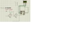
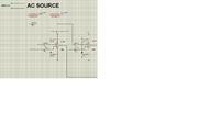
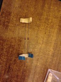
We have agreed to shunt a 200 ohm resistors to its output legs, then enter it to comparator biased circuit same as VT one; the problem is, even in its datasheet no statings were found to define the input from output terminals, so using a DVM, i made a resistivity check for both two sides: on the front two legs, the resistance was too high (O.L) on the rear two legs, the resistance was of 150 ohms, doens't this mean that the front legs must be connected in series with the fan, and the rear legs must be shunted with the burden and connected to LM358 circuit?
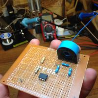
Something does not look right. For the current transformer, the input side should be having a very low resistance because that will take a high current. The resistance should be less than 1R because at 10A it will dissipate 100W. The output side (secondary side) resistance will be of the order of 10-100R (can be even 1K) because it will be loaded with a resistor to convert the current into a voltage. If one winding is showing very high resistance (OL), the winding is perhaps open. Can you please post a picture of the CT you are using?
- - - Updated - - -
I think you need to pass the current carrying conductor through the hole in the transformer and use the output from the winding showing 150R. Leave the two legs without continuity open.

