KhaledOsmani
Full Member level 6

Hello
I have a PIC18F4520, connected to a 16*4 LCD. [Properly working].
I have an 10'' square fan, with 0.06/0.08Amps, 220/240V, 50Hz, properly working.
I want to measure digitally the power factor of the fan, under all possible circumstances (voltage fluctuations, source dampings, etc..).
I've read about Zero Crossing Detection Method, that enters the analogue quantities of voltage/current consumed by the inductive load (fan), uses LM358 (op-amp), then using a specific code, it sets a timer, from the moment the voltage tends to 0, until current tends to 0, then according to this timer, pf is calculated as delay between voltage and current crossing zero.
I have found the following related link: https://microcontrollerslab.com/power-factor-measurement-using-microcontroller/
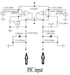
The above link, uses img1 as prototype schematic, where a shunt transformer from 240 to 5V, is connected between fan terminals, and a series current transformer is also connected between one terminal of the fan.
The two terminals of the two transformers, are connected to current/voltage limiter of 4kohms, then fed into an LM358 opamp, then directly connected to analogue input of PIC (in the link the PIC used is PIC16F877).
My first question is, is that circuit (img1) safe to use? I didn't see any bridge rectifiers, and signals are assumed to still be AC, so how come they can be fed into the PIC? Plus only in AC zero crossing takes place, how come in DC (after supposed rectification that must be done) we can know that the AC version of the signal crossed zero?
Also if the circuit is safe, and ideal to be practiced, what is the current transformer ratings? what is the maximum input current to the PIC analogue pin?
Thanks


