Continue to Site

Welcome to EDAboard.com

Welcome to our site! EDAboard.com is an international Electronics Discussion Forum focused on EDA software, circuits, schematics, books, theory, papers, asic, pld, 8051, DSP, Network, RF, Analog Design, PCB, Service Manuals... and a whole lot more! To participate you need to register. Registration is free. Click here to register now.

Power Amplifier Design - Revision

Status
Not open for further replies.
But the others will think the diodes are separated from the transistor but they are integrated in a singla package..
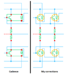
Then show them in the package without using extra confusing wires, like this:
 

Attachments

  • Cadence amplifier schematic again.png
    Cadence amplifier schematic again.png
    7.3 KB · Views: 83

Why not a 2 or 4 ohm load and a lower supply voltage? Transistors with such a high voltage are even more expensive. Take into account that biading diodes are thermally connected to the heat sink to avoid distortion and compensate the transistors temperature variations simultaneously.

The power supply will be expensive too, and it will get a bit hot at maximum power, do all the calculations to avoid damages.
 

The speakers in my car are 2 ohms and the amplifiers are bridged so that the power can be pretty high when powered from only a 12V battery.
 

117211d1419398608t-amplifier.png


What do that transitor as driver? I don't know how analyze it. I put the same transistor but it reduces the amplitude. How I must to polariza it?

circuit.png

In that case it has as offset -70[V] DC, so there must be a polarization.
 

Since R3 is to large to drive the base and diodes, it must be reduced to feed assuming worst case hFE, which may be 30% of nom. At low Vce (2V), which is the minimum you want to output for max Pout.

So if Vmax= 68V to 8 ohms at beta=50, driver must handle 400 ohm load , then previous stage, 2K load etc. but no more than 3 emitter followers typically as Vbe drop is costly so 4th driver uses complementary open collectors to rails. With crossover base drive current source.

in your simple design, not enough base drive and too much base R loss.


When input is negative the Rdiode bias worst case will result in excess power dissipated on pull up, so many cascade stages assuming beta=50 for a nominal value of 150 roughly, are needed.

then your output Re can reduce to 0.1 or 0.05 and negative feedback overall gain lowers output impedance by Vgain amount, to give better bass response and high "dampening value " or impedance to load ratio and lower THD.

note in audioguru's excellent design, there are only two emitter follower stages in output with compl. open collectors driving Q4,Q7,Q8 on high side, same for low side. Then with all these stages AND negative feedback parasitic oscKILLation can fry the outputs so a series cap and same R value as load works to suppress this above 20kHz. Running without thus and no load speaker will ruin Amp.but with this protection will save it from no load.
 
What is the input impedance? I thought it is 10[komhs] in paralel with hie+(0.1+8)

but i did not take in care the Rdiode, what value is it?

So the input impedance is

10 Kohms in paralel with Rdiode and that in paralel with Rl+Re

that 's right?
 

When the output into the speaker is only +50V then the 10k resistor provides the diodes and NPN output transistor base with a current of only (70V - 50V)/10k= 2mA. But its collector and emitter current is 50V/8 ohms= 6.25A. Its minimum hFE is 15 so the base current should be 6.25A/15= 417mA and the value of the 10k resistor should be (70V - 50V)/417mA= 48 ohms which is ridiculous. You need emitter-follower driver transistors to make darlington transitors or Sziklai pairs for the output transistors.

You have a huge offset voltage because the input transistor has its emitter at -70V and its base floating or at 0V. The base needs to be biased properly.
 

What is the input impedance? I thought it is 10[komhs] in paralel with hie+(0.1+8)

but i did not take in care the Rdiode, what value is it?

So the input impedance is

10 Kohms in paralel with Rdiode and that in paralel with Rl+Re

that 's right?

Diode ESR starts and 10 Ohms for 0.1 W types and 1 Ohm for 1W types and rises with lower current, It is in series with R pullup,,which using fixed R is the wrong way to design this.
 

In left are the equivalent ac circuit for one transistor. Do you means is like that?

circuit.png
 

Attachments

  • circuit.png
    circuit.png
    16.5 KB · Views: 70

I think now is working, for a 300[mV] input signal the output signal is 30[V]

circuit.png
 
Last edited:

Now you simulate a transistor (the driver transistor?) with its emitter grounded so it cannot drive the output transistors to a negative voltage. It also has no positive power supply so it also cannot drive the output transistors to a positive voltage.
If your speaker is 600 ohms then you can use only one driver transistor. With an 8 ohms or less speaker then you need a pair of driver transistors and probably paralleled output transistors. The driver transistors will be fed from a pre-driver transistor or a differential pair that provides the voltage gain.

Why are you using huge diodes that are rated at 35A?

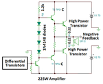
I think you should learn about high power amplifiers (there are thousands in Google) and design one something like this:

- - - Updated - - -

You posted a pre-driver transistor with a very low value collector resistor value. The resistor will be red hot dissipating 24.5W and the poor little TIP31 transistor will also cook itself with 24.5W.
There is not nearly enough base current so the transistor will be almost cutoff with a very high collector voltage and will not amplify anything.
 

Attachments

  • Power amplifier.png
    Power amplifier.png
    14.8 KB · Views: 78
  • transistor.png
    transistor.png
    12.1 KB · Views: 73
Using R11=40KOhms there is Ic=0.233 and P=11[W]. I think if I make the 200Ohms with two resistor of 100Ohms, I can use a resistor of 10 [W], because there will be 5.5[W] for each one.
 
Last edited:

Status
Not open for further replies.

Similar threads

Part and Inventory Search

Welcome to EDABoard.com

Sponsor

Back
Top