Continue to Site
Follow along with the video below to see how to install our site as a web app on your home screen.
Note: This feature may not be available in some browsers.

do{
for(i=0;i<4;i++){
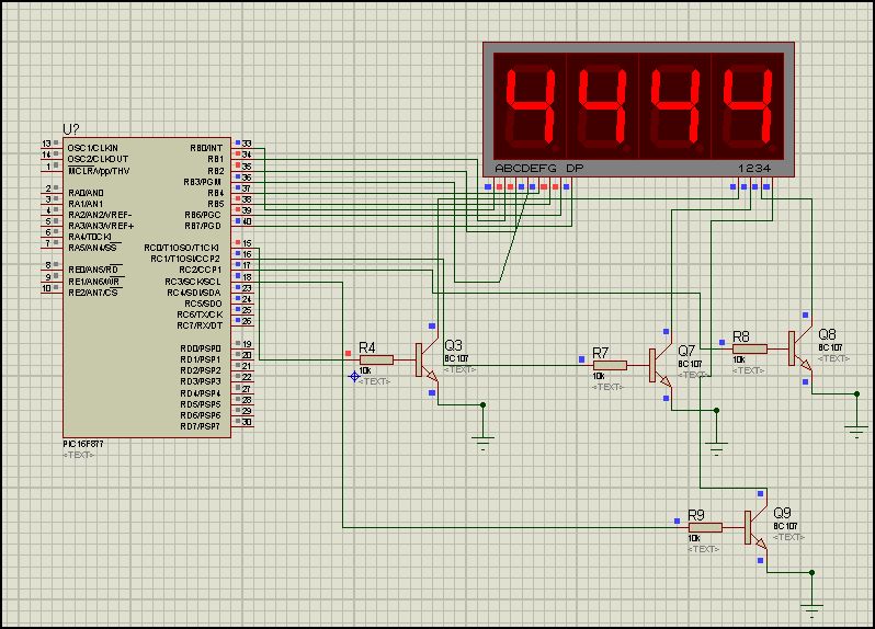
PORTC = 0 ;////This is the port which has the common cathodes connected to it via transistor
PORTb = mask(disp[i]); ///////'This is the data port
//PORTC.f(i) = 1; ////////////////'RC0 = 1st display, RC3 = 4th display
PORTC| = (1<<i);//
delay_ms(10); /////////////'Delay between successive changing. If other stuff are to be done during this time, use timer for delay
}
}while(1);unsigned short mask(unsigned short num) {
switch (num) {
case 0 : return 0x3F;
case 1 : return 0x06;
case 2 : return 0x5B;
case 3 : return 0x4F;
case 4 : return 0x66;
case 5 : return 0x6D;
case 6 : return 0x7D;
case 7 : return 0x07;
case 8 : return 0x7F;
case 9 : return 0x6F;
} //case end
}//~
unsigned short temp,disp[]={1,2,3,4},i ;
void main() {
adcon1=7;
//ansel=0;
//anselh=0;
INTCON = 0;
//C1ON_bit = 0; // Disable comparators
//C2ON_bit = 0;
PORTB=0;
TRISB=0;
portc=0;
trisc=0;
disp[0]=1;
disp[1]=2;
disp[2]=3;
disp[3]=4;
do{
for(i=0;i<4;i++){
PORTC = 0 ;////This is the port which has the common cathodes connected to it via transistor
PORTb = mask(disp[i]); ///////'This is the data port
//PORTC.f(i) = 1; ////////////////'RC0 = 1st display, RC3 = 4th display
PORTC| = (1<<i);//
delay_ms(10); /////////////'Delay between successive changing. If other stuff are to be done during this time, use timer for delay
}
}while(1);
}
") )
)