Continue to Site

pic16F887 with lm016l LCD problem

Status
Not open for further replies.

timi

Junior Member level 2
Joined
Feb 28, 2006
Messages
23
Helped
0
Reputation
0
Reaction score
0
Trophy points
1,281
Activity points
1,422
hi guys,

i and just trying to get the rs232 data out to the LCD by using the pic16F887. i made a test program for this and i have searched around and came up with this code:

Code:
include "D:\Projects\asdfasdsa.h"
//#include <LCD.C>


#define LCD_ENABLE_PIN  PIN_B5                                    ////
#define LCD_RS_PIN      PIN_B4                                    ////
#define LCD_RW_PIN      PIN_E2                                    ////
#define LCD_DATA4       PIN_B0                                    ////
#define LCD_DATA5       PIN_B1                                    ////
#define LCD_DATA6       PIN_B2                                    ////
#define LCD_DATA7       PIN_B3 

//#define LCD_TYPE 2
#include <lcd.c>
void main()
{
   lcd_init();
   
   lcd_putc("\a");
   lcd_putc("\F TEST");
   delay_ms(100);
   lcd_putc("\f asd");
   lcd_putc("\f asdsa");

   setup_adc_ports(NO_ANALOGS|VSS_VDD);
   setup_adc(ADC_CLOCK_DIV_2);
   setup_spi(SPI_SS_DISABLED);
   setup_timer_0(RTCC_INTERNAL|RTCC_DIV_1);
   setup_timer_1(T1_DISABLED);
   setup_timer_2(T2_DISABLED,0,1);
   setup_ccp1(CCP_OFF);
   setup_comparator(NC_NC_NC_NC);// This device COMP currently not supported by the PICWizard
   lcd_init();

   //TODO: User Code

}
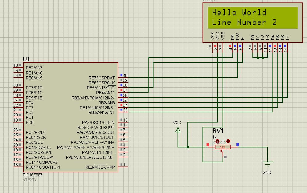
the schematic is like this:
pic16F887-lcd.JPG

please can someone help as on the software sim it is not working.

thanks,

Timi
 

Hi jjeevan007


i have ccs pcm 4.107
 

Are you simulating the above program in proteus? or you have posted it for example.
Hardware:
Schematic you have posted doesn't work.
LCD pins 2, 5, 7, 8, 9, 10 should connect to ground.
uC pin1 MCLR should be high. So connect to +5V.
Also, you must mention frequency for microcontroller. Right-click and check in properties.

software:
No header files included.
No clock frequency mentioned
You are using PORT B. So in your LCD.c, you must configure according to that.

Best wishes :)
 

post the full code include lcd.c file otherwise i code for hitech complier if u want i can share...........
 

Hi Guys thanka lot for the help.

i searched the net without expecting to find such a very fast support here. i got it working now. the code for main file and ldc driver + the schematic that works for me:

it has a lot of crap as i was trying to get it work so dont blame ME :p.

Code:
#include "D:\documents and settings\Administrator\Application Data\PICC\Projects\asdfasdsa.h"
//#include <nokia.h>
//#include <LCD.C>


#define LCD_ENABLE_PIN  PIN_B5                                    ////
#define LCD_RS_PIN      PIN_B4                                    ////
#define LCD_RW_PIN      PIN_b7                                    ////
#define LCD_DATA4       PIN_B0                                    ////
#define LCD_DATA5       PIN_B1                                    ////
#define LCD_DATA6       PIN_B2                                    ////
#define LCD_DATA7       PIN_B3 

//#define LCD_TYPE 2
#include <flexy-ldc-driver-tt-24-01-2013.c>
void main()
{
   {
   //output_high(LCD_POWER);  // Turn on power to LCD
   //output_low(LCD_RW);      // Set R/W pin on LCD to a low level

lcd_init();              // Initialize the LCD

lcd_putc("\fHello World\n");
lcd_putc("Line Number 2");

while(1);
} 

   setup_adc_ports(NO_ANALOGS|VSS_VDD);
   setup_adc(ADC_CLOCK_DIV_2);
   setup_spi(SPI_SS_DISABLED);
   setup_timer_0(RTCC_INTERNAL|RTCC_DIV_1);
   setup_timer_1(T1_DISABLED);
   setup_timer_2(T2_DISABLED,0,1);
   setup_ccp1(CCP_OFF);
   setup_comparator(NC_NC_NC_NC);// This device COMP currently not supported by the PICWizard
   lcd_init();

   //TODO: User Code

}

the flexy ldc driver a copied from **broken link removed** and renamed it flexy-ldc-driver-tt-24-01-2013.c
Code:
//coder: PCM Programmer
#define LCD_DB4 PIN_b0
#define LCD_DB5 PIN_b1
#define LCD_DB6 PIN_b2
#define LCD_DB7 PIN_b3

#define LCD_E PIN_b5
#define LCD_RS PIN_b4
#define LCD_RW PIN_b7

#define LCD_CGRAM_ADDR 0x40
#define LCD_DDRAM_ADDR 0x80

#define USE_LCD_RW 1

#define lcd_type 2

#define lcd_line_two 0x40

#define LCD_CHAR_1 0x01
#define LCD_CHAR_2 0x02
#define LCD_CHAR_3 0x03
#define LCD_CHAR_4 0x04
#define LCD_CHAR_5 0x05
#define LCD_CHAR_6 0x06
#define LCD_CHAR_7 0x07
#define LCD_CHAR_8 0x08

int8 const LCD_INIT_STRING[4] =
{0x20 | (lcd_type << 2),0xc,1,6};

void lcd_send_nibble(int8 nibble)
{
output_bit(LCD_DB4, !!(nibble & 1));
output_bit(LCD_DB5, !!(nibble & 2));
output_bit(LCD_DB6, !!(nibble & 4));
output_bit(LCD_DB7, !!(nibble & 8));
delay_cycles(1);

output_high(LCD_E);
delay_us(2);
output_low(LCD_E);
}

#ifdef USE_LCD_RW

int8 lcd_read_nibble(void)
{
int8 retval;

#bit retval_0 = retval.0
#bit retval_1 = retval.1
#bit retval_2 = retval.2
#bit retval_3 = retval.3
retval = 0;

output_high(LCD_E);
delay_cycles(1);

retval_0 = input(LCD_DB4);
retval_1 = input(LCD_DB5);
retval_2 = input(LCD_DB6);
retval_3 = input(LCD_DB7);

output_low(LCD_E);
return(retval);
}

#endif

#ifdef USE_LCD_RW

int8 lcd_read_byte(void)
{
int8 low;
int8 high;

output_high(LCD_RW);
delay_cycles(1);
high = lcd_read_nibble();
low = lcd_read_nibble();
return( (high<<4) | low);
}

#endif

void lcd_send_byte(int8 address, int8 n)
{
output_low(LCD_RS);
#ifdef USE_LCD_RW

while(bit_test(lcd_read_byte(),7)) ;
#else
delay_us(60);
#endif

if(address)
output_high(LCD_RS);
else
output_low(LCD_RS);
delay_cycles(1);

#ifdef USE_LCD_RW
output_low(LCD_RW);
delay_cycles(1);
#endif

output_low(LCD_E);
lcd_send_nibble(n >> 4);
lcd_send_nibble(n & 0xf);
}

void lcd_setcursor_vb(short visible, short blink) {
lcd_send_byte(0, 0xC|(visible<<1)|blink);
}

void lcd_init(void)
{
int8 i;

output_low(LCD_RS);

#ifdef USE_LCD_RW
output_low(LCD_RW);
#endif

output_low(LCD_E);
delay_ms(15);

for(i=0 ;i < 3; i++)
{
lcd_send_nibble(0x03);
delay_ms(5);
}

lcd_send_nibble(0x02);
for(i=0; i < sizeof(LCD_INIT_STRING); i++)
{
lcd_send_byte(0, LCD_INIT_STRING[i]);

#ifndef USE_LCD_RW
delay_ms(5);
#endif
}
}

void lcd_gotoxy(int8 x, int8 y)
{
int8 address;
if(y != 1)
address = lcd_line_two;
else
address=0;
address += x-1;
lcd_send_byte(0, 0x80 | address);
}

void lcd_putc(char c)
{
switch(c)
{
case '\f':
lcd_send_byte(0,1);delay_ms(2);break;
case '\n':lcd_gotoxy(1,2);break;
case '\b':lcd_send_byte(0,0x10);break;

default:
lcd_send_byte(1,c);break;
}

}

#ifdef USE_LCD_RW

char lcd_getc(int8 x, int8 y)
{

char value;

lcd_gotoxy(x,y);
while(bit_test(lcd_read_byte(),7));
output_high(LCD_RS);
value = lcd_read_byte();

output_low(lcd_RS);
return(value);
}

#endif

clock is internal 4Mhz for the ccs project and on proteus is set to default "just deleted the 1Mhz entry that was there by default"

i changed the schematic to this one changing the pin of #define LCD_RW_PIN PIN_b7 on the main file and into the schematic
VSS is not connected and the VDD is connected to VCC


for the files on proteus i need to upload somewhere

thanks a lot guys i have learned so much here.

TIMI

- - - Updated - - -

Guys, how do i output the long int and int variables to the LCD??? :)
 

Guys, how do i output the long int and int variables to the LCD??? :)

- - - Updated - - -

found it :)
 

Status
Not open for further replies.

Part and Inventory Search

Welcome to EDABoard.com

Sponsor

Back
Top