Continue to Site

Welcome to EDAboard.com

Welcome to our site! EDAboard.com is an international Electronics Discussion Forum focused on EDA software, circuits, schematics, books, theory, papers, asic, pld, 8051, DSP, Network, RF, Analog Design, PCB, Service Manuals... and a whole lot more! To participate you need to register. Registration is free. Click here to register now.

PIC16F1936 variable duty cycle with lookup table and potentiometer

Status
Not open for further replies.
That is how I did and it shifts sine wave 2 and 3 but the angle starts from 120 and 270 degrees for sine 1 and sine 2 and it keeps on shifting and cycling.
 

Tables A and C are identical and the angles should be 0, 120 and 240 degrees. I think you probably spend too long in the ISR with all those calculations but I couldn't find a way of timing the period between the start and return of the ISR in MikroC. In fact I couldn't get the ISR to execute at all, MikroC debugging is very poor.

Brian.
 

Hello betwixt, could you adjust those tables and show how they might be arranged so that the 120 degrees be implemented?? I tried by taking

Phase _1:from 0 to 33th
Phase_2:from 11th to 33th and then 0 to 10th
Phase_3:from 22th to 33th and then 0 to 21th
but not succeeding with proper phase shifting

I modified a little bit the functions of pin and now I set


APFCON=0X00

Then pins functions became as follows:

CCP1►RC2
CCP2►RC1
CCP3►RC6

As stated before the three phase induction motor has to be controlled with V/F maintained constant and the speed variation has to be done using a potentiometer on RA0 (AN0) of PIC16F1936.

Please help to handle.

see the file attached with proteus simulation
 

Attachments

  • Simulation_Outcome.zip
    311.7 KB · Views: 110

I can see no point to using three tables with the same set of numbers in them.

I've put together a spreadsheet to show how the values are produced. I used LibreOffice 'Calc' but i've attached an xlsx conversion as well. I can't tell if the .xlsx works as I'm not using Excel. It only has very basic error checking, make sure the numbers it produces for 90, 180 and 270 degrees look sensible before you use them!

How to use it:
1. In the yellow A1 box put the number of points along the sine wave you want to produce values for. The number must be greater than zero, less than 360 and directly divisible into 360.
2. The colums are:
'A' - is the angle in degrees
'B' - is zero or the same as 'A' if the angle is going to be used in the calculation
'C' - is the sine of the angle
'D' - is the sine value scaled from -127 to +127
'E' - the same as 'D' but normalized to be between 0 and 254 (so it fits in 8-bits)
'F' and 'G' - are the rounded decimal and hexadecimal values to generate PWM with highlighting on the ones to use.
 

Attachments

  • PWM_Spreadsheets.zip
    57.1 KB · Views: 122

Hello,are those F and G values the entries for our three tables?or only single table?Why can`t you help us by proving the right three LUT?I do have the same excel document with proper values but the problem is to decompose in the three LUT or maintaining one LUT and use software features for implementing the phase shift!!

Reagrds,
 

:bang::bang::bang: The ONE table contains all the values. It holds the values needed for all three phases so why do you think more tables are needed?

Think about it - the table defines the shape of the sine wave. Think of it like a graph, if you start at the begining (0 degrees) and work down to the end it will plot the points of a sine wave.

Now start reading the table one third of the way down from the top, when you get to the end loop around to the start and keep going. Plot the points, what do you get?
Next start reading from two thirds of the way from the top and again loop to the start when you reach the end. Plot the points, what do you get?

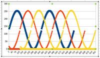
If you did it right and plot the three lines on the same scale, you get three sine waves shifted 120 degrees apart - isn't that what you want?

If you do that and use the values in the column F or G (they are the same but in different radix) for each PWM generator you will produce a 3-phase sine wave.

Brian.

---added---
Graphic to prove it. I copied the shifted data and didn't quite line it up on the correct row so there is a slight step in the waveform. I copied it over several cycles, the angle in degrees is the bottom scale and PWM value is on the side scale.


so how our codes should be edited for indexing so that the graphs,should look as you specified?

Regards,
 

I think all this was explained a long time ago!

The table contains the PWM settings to produce a sine wave. If you start at the beginning of the table it will plot one of the sine waves, let's call that phase_1. If you start reading the same table at the 120 degree point, it will plot a sine wave shifted by 120 degrees, let's call that phase_2 and if you start at the 240 degree point it will plot a sine wave shifted by 240 degress, let's call that phase_3.

*** Note it is the STARTING POINT that is different, not the contents of the table itself ***

The table is stored in an array, let's call that "Sine_Table" and let's call the entries in the table "Sine_Table[0]", "Sine_Table[1]", "Sine_Table[3]" and so on for as many entries as the table contains. So each point in the waveform is represented by one of those numbers in [ ] which we call it's "index".

For example, if the table has 60 entries, and we use an index of 0 it will select the value at "Sine_Table[0]", if we used index 22 it would select the value at "Sine_Table[22]", the same applies to all the other index numbers up to the last one which is "Sine_Table[59]".

So for a table with 60 entries representing 360 degrees, index 0 will point to the value at the start of the table, index 19 will point to a value representing 120 degrees and index 39 will point to the value representing 240 degrees.

If Sine_Table[0] value is fed to PWM generator 1 it will produce a voltage proportional to the value - thats phase_1
If Sine_Table[19] value is fed to PWM generator 2 it will produce a voltage proportional to the value - thats phase_2
If Sine_Table[39] value is fed to PWM generator 3 it will produce a voltage proportional to the value - thats phase_3

That's fine for those particular values but you need to cycle through the table in order to make the sine wave shape. Replace the fixed index numbers with a variables instead, lets call them p1_index, p2_index and p3_index. If p1_index is set to zero, p2_index is set to 19 and p3_index is set to 39 it would produce exactly the same values as above.

Being a variable, we can easily change it's value. If you set the starting values of p1_index to zero, p2_index to 19 and p3_index to 39 you could get those same values with:
PWM1 value = Sine_Table[p1_index]
PWM2 value = Sine_Table[p2_index]
PWM3 value = Sine_Table[p3_index]

But that's still a single value for each generator. Now look what happens when you add one to the index values, they become:
PWM1 value = Sine_Table[1]
PWM2 value = Sine_Table[20]
PWM3 value = Sine_Table[40]

Each time you add 1 to the indexes, it makes all three PWM generators produce the next voltage from their respective positions in the table. We are starting to make a 3-phase waveform, all we need to do it repeat the process until the end of the table.

Next problem: because the three index values start differently, they will reach the end of the table at different times. What you need to do is check when the last entry in the table has been used then go back to the start of the table again (index zero). If you keep doing that for each of the indexes you produce a continuous waveform. Effectively, the three index values 'chase' each other around the table with a spacing of one third of the table between them.

The initial values of the three indexes decides the phase shift between the waveforms and how fast you step them through the table decides the frequency.

Brian.
 

This is my latest code and sine waves are shifting. They are not maintaining 120 degrees. Simulation screenshot is included in the attachment. Proteus 8.2 SP2 format file is included. What is the mistake ?
 

Attachments

  • 3 Phase SPWM.rar
    122.1 KB · Views: 105

Just to prove the point, I wrote a short program using one LUT and three pointers, reading the ADC to set the frequency. I do not have any 16F1936 to hand so I used a similar device, the 16F1827 instead. It worked fine, produced three PWM waveforms with fixed 120 degree phase shift and was tunable from about 22Hz to about 40Hz.

Note: It is NOT written in MikroC and for convenience I used a RAD tool to write it quickly. The interrupt routine isn't shown (the RAD adds it in the background) but all it does is check the interrupt bits and call the routine as necessary.
Code:
#include "C:\\projects\\3Phase_PWM\\3phase_PWM_Auto.h"

unsigned char P1_index, P2_index, P3_index; // pointers to sine table 
unsigned char TableSize; // number of entries in the sine table
int FrequencyValue = 0;

const unsigned char Sine_Table[90] = {127,136,145,153,162,170,179,187,194,202,209,215,
221,227,232,237,241,245,248,250,252,253,254,254,253,252,250,248,245,241,237,
232,227,221,215,209,202,194,187,179,170,162,153,145,136,127,118,109,101,92,
84,75,67,60,52,45,39,33,27,22,17,13,9,6,4,2,1,0,0,1,2,4,6,9,13,17,22,27,33,
39,45,52,60,67,75,84,92,101,109,118};


//*******************************************************************************
//
void UserInterrupt()
{
 #asmline SETPCLATH UserIntReturn,-1  ; SETPCLATH for interrupt routine
 #asmline goto UserIntReturn	      ; Assembler - go back to interrupt routine
}

//*******************************************************************************
//
void UserInitialise()
{
	TableSize = sizeof(Sine_Table);

	P1_index = 0; // reference phase angle =  0 degrees
	P2_index = TableSize / 3; // phase angle = 120 degrees
	P3_index = P2_index * 2; // phase angle = 240 degrees

	ADCON0 |= (1 << ADGO);	// start a new conversion
}

//*******************************************************************************
//
void UserLoop()
{
}

//*******************************************************************************
// called when ADC conversion is complete
void ADC_Finished()
{
	FrequencyValue = ((int)ADRESH << 8) + (int)ADRESL; // full ADC result
	FrequencyValue >>= 4; // scale to 8-bits
	ADCON0 |= (1 << ADGO);	// start a new conversion
}

//*******************************************************************************
// called when timer 0 overflows
void T0_Overflow()
{
	if(++P1_index == TableSize) P1_index = 0; // point to next sine value
	if(++P2_index == TableSize) P2_index = 0;
	if(++P3_index == TableSize) P3_index = 0;
	
	SetPWM1Volts(Sine_Table[P1_index]);
	SetPWM2Volts(Sine_Table[P2_index]);
	SetPWM3Volts(Sine_Table[P3_index]);
	
	TMR0 = FrequencyValue; // reload with sine stepping rate
}
Brian.
 

I made it. See images. mikroC PRO PIC and Proteus 8.2 SP2 format files included.
 

Attachments

  • 3 Phase SPWM - PIC16F1936 - 20 MHz Clock - 10 KHz SPWM - Phase Shifted - Rev 3.rar
    113.7 KB · Views: 106
  • Simulation Screenshot 4.png
    Simulation Screenshot 4.png
    139.3 KB · Views: 122
  • Simulation Screenshot 3.png
    Simulation Screenshot 3.png
    139.9 KB · Views: 117
  • Simulation Screenshot 2.png
    Simulation Screenshot 2.png
    139.5 KB · Views: 116
  • Simulation Screenshot 1.png
    Simulation Screenshot 1.png
    145.5 KB · Views: 115

Hello betwixt,have you tried physical implementation??You know for induction motor control a multiplication and division operations are very important,have you tried to provide those,as the increase in voltage has to go with increase in frequency in order to have V/F which is a constant!!

What has been posted #52 I tried to use it with PIC16F1936 but the PWM is adjusting itself the duty can`t stabilize so I don`t even know if the frequency is stable at some level. could anyone help to handle(in simulation with proteus it works fine but on the board it can`t the duty keeps changing itself)!!


Regards
 

Well, that's the first time in #53 posts you mentioned it is for motor control. I don't have three power amplifiers and a 3-phase motor on my work bench so no, I didn't test it that way. I assume the motor is synchronous so the rate the PWM ratio varies is what decides the motor speed. If more or less voltage is needed that's a different issue. Not all multi-phase generators are used in motor control, I recently designed and built a 5-phase sine generator for a customer.

Brian.
 

Can you suggest the way forward for generating those 3PWM in case of motor control with V/F constant?

Thank ou
 

Assuming you actually need to maintain constant torque, there are two methods:
1. adjust the low and high PWM values according to the speed so the resulting voltage changes,
2. keep the PWM the same and adjust the DC supply to the PWM drivers.

For method 1, you have to decide the voltages needed at lowest speed and scale the PWM figures accordingly. Then multiply the table values by a figure derived from the speed before sending them to the PWM generators. Make sure the multiplied number does not exceed the maximum to PWM can accept or you will get a 'wrap around' effect in the voltage and severe waveform distortion.

For method 2. you need a method to control the DC source to the motor drivers, this could be another PWM signal or a signal generated by any other analog means. As the frequency increases, the DC supply should be increased in proportion.

There is a good reference at **broken link removed** but the code examples are for TI DSP products. The flow charts and text will explain the principles quite well.

You also need to decide whether you are simply producing a constant V/F and hoping the motor responds or if you are going to employ a feedback mechanism to combat load variations.

Brian.

Dear Brian,I have a reference from microchip using assembly,I want to adapt my 16F1936(I am using this I can`t find the PIC16F777) from 16f777 (which was used for coding by microchip),so I am struggling in handiling the instructions equivalence but not succeeding for the last two weeks,
 

All the basic 16F processors use the same instruction set so if you set the assembler to the correct device so it knows the new register locations the code should be almost identical. The only thing to watch for is the 16F1xxx series use an extended architecture which automatically saves and restores the W and STATUS registers when an interrupt occurs so you can safely remove some lines at the start and end of the ISR. This kind of application is better suited to the 18F series of processors which have instructions to support look-up tables as well as running slightly faster. The problem you may have with 16F is that if a table crosses a page boundary, it will try to loop back to the beginning of the same page instead of continuing into the next one. It's unavoidable when you only have 8-bit registers and adding the extra code to check the boundary will slow down the look-up operation and limit the top frequency you can achieve.

Brian.
 

I didn`t find fruitful info on using program memory that is why I am would like to use EEPROM
 

EEPROM is great for storing settings that might change occasionally or for serial numbers. It isn't suitable for storing variables which can change often because EEPROM storage has a limited number of usage cycles.

PIC16F136 has 8K of program memory and 512 bytes of RAM, that should be more than enough for your application without needing to touch the 256 bytes of internal EEPROM. If you want to use external EEPROM devices, remember you need to write code to interface to them and they will be considerably slower to access.

What is the problem you have with using program memory?

Brian.
 

Status
Not open for further replies.

Similar threads

Part and Inventory Search

Welcome to EDABoard.com

Sponsor

Back
Top