Continue to Site

Welcome to EDAboard.com

Welcome to our site! EDAboard.com is an international Electronics Discussion Forum focused on EDA software, circuits, schematics, books, theory, papers, asic, pld, 8051, DSP, Network, RF, Analog Design, PCB, Service Manuals... and a whole lot more! To participate you need to register. Registration is free. Click here to register now.

PFC Circuit issue using 28019

Status
Not open for further replies.

sabu31

Advanced Member level 1
Joined
Jan 28, 2011
Messages
467
Helped
12
Reputation
24
Reaction score
13
Trophy points
1,298
Activity points
5,359
Dear All,

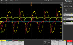
I am experimenting on a PFC circuit using UCC28019. The system turns on after AC input of 125V . And output is around 400V. However, the input current is not correcting. THe load used is 280 Ohms. I am attaching the waveform.
The input current is in Red. The output voltage is in Green. The input voltage is in yellow.

Though I have designed for 2kW.
The current sense resistor used is 0.05Ohms. Is it current sense hitting upper limit.
Please let me know what should be done to troubleshoot the system.
 

Attachments

  • Pfc_004.png
    Pfc_004.png
    179.6 KB · Views: 176

Hi all,

Thanks for the suggestions. The noise in input current was due to limited bandwidth of the probe used. I have also tested at double load of 1600W (as the devices were rated for this level). However, here some other issues of slight distortion current is there.
 

Attachments

  • scope_3.png
    scope_3.png
    60.5 KB · Views: 86

Again, hard to give any specific advice without seeing waveforms of Vcomp or Icomp.

Years ago I worked with a couple of TI's PFC controllers and overall I found that their tools for choosing component selection and compensation gave good results, but only if you fed it proper data. And there was a decent amount of ambiguity (like rms vs peak input voltage, etc), which would lead to things not quite working as expected.
 

The noise in input current was due to limited bandwidth of the probe used.
Thanks, but the limited bandwidth itself would not of caused the noise seen...if you changed probes and the noise went, then its likely because that probe has better common mode filtering in it....or is just better constructed such that common mode noise is not so much of a problem for it....perhaps it has a common mode choke incorporated within it.
 
Status
Not open for further replies.

Similar threads

Part and Inventory Search

Welcome to EDABoard.com

Sponsor

Back
Top