KerimF
Advanced Member level 5

- Joined
- May 17, 2011
- Messages
- 1,554
- Helped
- 376
- Reputation
- 760
- Reaction score
- 379
- Trophy points
- 1,373
- Location
- Aleppo city - Syria
- Activity points
- 13,095
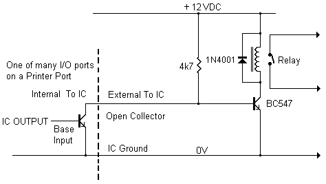
I think for a reason, unknown so far, your parallel output pin (before the diode 1N4148, that is at its anode) cannot be made low as you pointed out earlier:
You did measure Vbe which is likely about 0.6 to 0.7V only when the port is high. In other words, any time you have Vbe not close to zero, it means the port voltage is higher than 1V2. You can easily check this point.
So to test your external circuit and force your relay to turn off, just short the output port to ground (don't worry, the port is weak and the short current will be relatively too small, a few mA only.
Kerim
the voltage at parallel out before connecting the supply is above 3 volts dc...
You did measure Vbe which is likely about 0.6 to 0.7V only when the port is high. In other words, any time you have Vbe not close to zero, it means the port voltage is higher than 1V2. You can easily check this point.
So to test your external circuit and force your relay to turn off, just short the output port to ground (don't worry, the port is weak and the short current will be relatively too small, a few mA only.
Kerim
Last edited:


