Continue to Site

Welcome to EDAboard.com

Welcome to our site! EDAboard.com is an international Electronics Discussion Forum focused on EDA software, circuits, schematics, books, theory, papers, asic, pld, 8051, DSP, Network, RF, Analog Design, PCB, Service Manuals... and a whole lot more! To participate you need to register. Registration is free. Click here to register now.

[SOLVED] Parallel Port controlled circuit

Status
Not open for further replies.

Hussainb

Member level 2
Member level 2
Joined
Mar 18, 2011
Messages
46
Helped
8
Reputation
16
Reaction score
8
Trophy points
1,288
Visit site
Activity points
1,622
Hello respected members,
I wanted to control some electrical appliances using my pc parallel port...
so i looked up the net and got this simple circuit for my design...which i have uploaded

https://obrazki.elektroda.pl/2_1320245735.gif

and i am using lalim parallel port control software to control the port.
I got the components and built it on a vero board...
I am using a 12v relay in this circuit..

I thought of using the pc +12v supply for the relay but it didnt work so i used an external wall mount adapter which provides 15.60 volts DC on no load condition and drops to 14.35 when directly connected to relay and when the relay gets activated... the thing happening is that as soon i powerup the ckt using the adapter the relay switches on.... there is no effect of the change being made from the parallel port...

I checked that the software works properly and the o/p of port changes from .17 volts to 4.something when the data pin is selected.

Verified the circuit many times for errors... i havent connected the relay directly to supply, and there is no other error in building the circuit.


my only problem is that the relay switches on as soon as the external power supply is given..
pls help me understand the issue... thank you..
 

Attachments

  • imageview.gif
    imageview.gif
    4.2 KB · Views: 102

You should check, if the parallel port output voltage can be actually controlled by your software.
 

yes...the software controls the output voltage of the selected pin....
i have tested it using a multimeter....
the voltage changes from .17 volts to 4.something volts when activated.
 

Did you measure the voltage at the parallel out before connecting the 12V supply?
If the voltage is close to ground, then BC547 is likely shorted between collector and emitter.

Did you measure the DC resistance of the relay?

Kerim
 

Did you measure the voltage at the parallel out before connecting the 12V supply?
If the voltage is close to ground, then BC547 is likely shorted between collector and emitter.

Did you measure the DC resistance of the relay?

Kerim

the voltage at parallel out before connecting the supply is above 3 volts dc...
and i checked for shorts in circuit at collector and emitter as well performed a test on the transistor itself to see if its gone bad but no everything is fine...

and the dc resistance of relay is 0 .... no resistance in the coil..
all this is baffling me... everything is ok but why does the relay gets switched on...
do you think circuit is wrong?
thanks
 

and the dc resistance of relay is 0 .... no resistance in the coil..

That is not right at all, there should be a resistance of at least 100 ohm.
Make sure that you are using the correct relay pins.
Was this a 12v relay?
I hope it isn't a shorted coil.
 
Sorry... I didn't get what you mean that the DC resistance of the relay is 0 !!!
On the other hand, 3V at the input means that the port is ON and not off . The base current of BC547 is:
Ib= (3-1.4)/4.7 = 0.34 mA
Though it is somehow small but it might be enough to turn on your relay.

Kerim
 
That is not right at all, there should be a resistance of at least 100 ohm.
Make sure that you are using the correct relay pins.
Was this a 12v relay?
I hope it isn't a shorted coil.

yes its a 12 volt relay...
and i am using the right relay pins...
really, the resistance is 0, i measured just now using a meter..
and yes the realy switches on and off when 12 volts are directly given to it from the adapter..
relay is "sun hold RAS-1210"
here is its datasheet..
**broken link removed**
 

The datasheet says that the resistance of you coil is 400 ohm.
Are you sure that you are not getting a wrong measurement because of the diode?
 
Sorry... I didn't get what you mean that the DC resistance of the relay is 0 !!!
On the other hand, 3V at the input means that the port is ON and not off . The base current of BC547 is:
Ib= (3-1.4)/4.7 = 0.34 mA
Though it is somehow small but it might be enough to turn on your relay.

Kerim

yes when the port is triggered its op voltage is 3.something when connected to the ckt and 4.something when in open condition...
 

It is natural that your relay will be on as soon you apply on it 12V.
The base current is about 0.34mA and the relay current is 30mA.
The gain required:
30/0.34 = 88 which lets the saturation voltage be about 1V leaving 11V to the relay.

Kerim

Added:
Could you turn off the port by software so that its voltage be lower than 1.2V before applying the 12V?
 
Last edited:
The datasheet says that the resistance of you coil is 400 ohm.
Are you sure that you are not getting a wrong measurement because of the diode?

ok ok .... sorry
when i set the meter at its 2k range i get .419 as the reading of the coil...
it means the resistance is 419 ohms... i am really sorry.. i think i had the meter on the wrong setting just before..

---------- Post added at 21:14 ---------- Previous post was at 21:12 ----------

It is natural that your relay will be on as soon you apply on it 12V.
The base current is about 0.34mA and the relay current is 30mA.
The gain required:
30/0.34 = 88 which lets the saturation voltage be about 1V leaving 11V to the relay.

Kerim

Added:
Could you turn off the port by software so that its voltage be lower than 1.2V?

yes when i turn off the port its op is 0.17 volts... very less than 1.2 volts...
the output of the port pin is 3.something volts when the pin is set to high..i.e on..
 

The port output voltage in off state has been reported to be 0.17 V. Under this condition the relay should be clearly off. Also with a coil resistance of 400 ohm, there is no risk to overload the BC547 switch transistors. Thus the circuit behaviour still can't be explained. Some kind of wiring error must be expected.

To narrow the problem down, you should measure Vbe and Vce in control states on and off.
 
the voltage at parallel out before connecting the supply is above 3 volts dc...
As we saw earlier... in this case the relay should be turned on as soon as the 12V supply is connected.

Now do you get the same thing even if you set the parallel port voltage close to zero?

Kerim
 

The port output voltage in off state has been reported to be 0.17 V. Under this condition the relay should be clearly off. Also with a coil resistance of 400 ohm, there is no risk to overload the BC547 switch transistors. Thus the circuit behaviour still can't be explained. Some kind of wiring error must be expected.

To narrow the problem down, you should measure Vbe and Vce in control states on and off.

vbe and vce means that meter probes should be on base and emitter and collector and emitter respectively...
ok will do that.

---------- Post added at 21:47 ---------- Previous post was at 21:21 ----------

The port output voltage in off state has been reported to be 0.17 V. Under this condition the relay should be clearly off. Also with a coil resistance of 400 ohm, there is no risk to overload the BC547 switch transistors. Thus the circuit behaviour still can't be explained. Some kind of wiring error must be expected.

To narrow the problem down, you should measure Vbe and Vce in control states on and off.

these values are when external power is connected and relay is energised.
during port OFF state.
Vbe =0.635v
Vce =8.24v

during port ON
Vbe =0.665v
Vce=7.44v
 

Something is definitely wrongly wired. Mixing up emitter and collector of the transistors may be an explanation.

Should look like below:

56_1320251851.gif
 
Last edited:
Something is definitely wrongly wired. Mixing up emitter and collector of the transistors may be an explanation.

Should look like below:

56_1320251851.gif

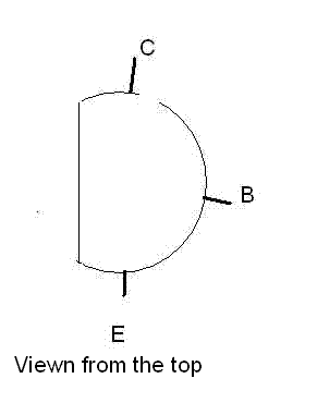
well, i have done the wiring refering the datasheet of the transistor...
But i rechecked and its ok...
Its dark here now,need to do other things..
Thank you for your time, will get back later.

---------- Post added at 22:37 ---------- Previous post was at 22:15 ----------

well, i have done the wiring refering the datasheet of the transistor...
But i rechecked and its ok...
Its dark here now,need to do other things..
Thank you for your time, will get back later.

I am sorry my mistake while measuring vbe...i took of vbc as i did it while eating..also i am a learner so get confused sometimes... thank you so much for spending your time.

corrected readings of Vbe are
OFF state 7.61v
ON STATE 6.78v
 
Last edited:

here is the guide from which i built the circuit..
i didnt post it before as the site was down from past few days
**broken link removed**
 

Status
Not open for further replies.

Part and Inventory Search

Welcome to EDABoard.com

Sponsor

Back
Top