Continue to Site

Welcome to EDAboard.com

Welcome to our site! EDAboard.com is an international Electronics Discussion Forum focused on EDA software, circuits, schematics, books, theory, papers, asic, pld, 8051, DSP, Network, RF, Analog Design, PCB, Service Manuals... and a whole lot more! To participate you need to register. Registration is free. Click here to register now.

Overshoot and undershoot of switched type digital signal

Status
Not open for further replies.

Junus2012

Advanced Member level 5
Joined
Jan 9, 2012
Messages
1,552
Helped
47
Reputation
98
Reaction score
53
Trophy points
1,328
Location
Italy
Visit site
Activity points
15,235
Hello friends,

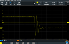
I have in my digital circuits outputs like digital signal from FPGA board or simple logic IC a practical bouncing when the output switch from one logic state to another state (from 0 to 1 or 1 to 0) as seen from the images below.
I have read from digital buffer data sheet a general note that if the output current drive capability is high, then this bouncing will be expected. I want to know from your experience how you treat it, because what I see from my eys that these over or undershoot magnitude are big enough to trigger the next logic stage.
The other question, why these peaking were not predictable by Cadence simulator.

Thank you in advance
BOUNC02.PNG


BOUNC1.PNG


Regards
 

Attachments

  • BOUNC1.PNG
    BOUNC1.PNG
    24 KB · Views: 264

Solution
I do not think you need an active probe, just make sure, if your using a DSO, your probes
are compensated both for G and response (DSOs generally have a routine to do this), and
you do the manual comp if also needed. Manuals have all this info.

No RC is needed in 99% of designs. Just attention to transmission line effects and loading
as Klaus has pointed out.

And make sure no kinks in probe cabling, and scope and probe connector to scope clean
and good contact. Lastly its ground lead length major contributor to this problem as
videos pointed out. And transmission line loading, and layout (you can "kink" a PCB
transmission line trace and create a lot of problems). Ap note son web on this topic.


Regards, Dana.
A divider network which loads the signal source "acceptably little"
and line-matches, can remove the majority of LC. Maybe 4950
ohms into 100 up, 100 down for a 100:1 nice round number,
and sub-mA signal burden. You could tweak in a bit of feedforward
C for edge sharpness but it'd be small, maybe hand whittled.
 

    Junus2012

    Points: 2
    Helpful Answer Positive Rating
If your signal source tolerates e.g. 1k resistive load, a 950 ohm series resistor with 50 ohm coax connector offers best signal quality to price trade-off. Your RTM3004 surely provides 50 ohm input option.
 
Thank you friends for your answer,

I am little confused, in the first the 10:1 probe was recommended because which has highest input impedance of 10 M Ohm,
Now you are suggesting to interface to 50 Ohm of my oscilloscope,
Yes my oscilloscope support the 50 Ohm interface.

Do I understand from you that connecting a regular oscilloscope probe has different requirement from connecting a coaxial cable and that is why you are suggesting the 50 Ohm setup.

My designed amplifier can support load of 10k Ohm, but 1k Ohm is little difficult

Thank you
 

Hi,

High frequency is different.

There are several problems.
* a proper HF cable/trace has a known (designed) characteristic impedance.
* and it needs a proper termination, else it causes echos.

A standard scope probe (1:1) maybe has a cable impedance of 50 Ohms and no termination (= high ohmic) at the scope.
Thus it´s basically not suitable for HF measurements. You may use it for DC and low frequency measurements.

You may switch ON the scope internal termination of 50 Ohms (a real resistor) then it may cause no echos, but it is rather low impedance and makes it not suitable for DC and low frequency. Indeed here not the frequency is the problem, but the voltage. Even 12V @ 50 Ohms cause a loss (heat) of about 3W.
Also this low impedance causes high current which may "modify" the signal you want to measure. Let´s say you measure a node with 100 Ohms source impedance (a microcontroller GPIO for example) and you laod it with (additional) 50 Ohms then the voltage will be drastically reduced. So the signal with and without the scope probe is not the same. --> invalid measurement method.

So what you want is:
* a probe which draws relatively low current (not to modify the signal/node you want to measure)
* but a low ohmic (source) to properly dirve the cable impedance (and termination)

You can do this with an amplifier. --> active probe

Or you can use a passive probe with built in divider.
FvM talked about 950 Ohms / 50 Ohms divider.
This solution results in
* a 1000 Ohms load to the signal (usually no problem to drive. Causes just minor modifications)
* a 47.5 Ohms source impedance ( 950 Ohms || 50 Ohms) for properly driving the cable.
* the voltage to be divided 39:1 (HF, properly terminated)
(50 Ohms of the resistor divider in parallel to the 50 Ohms characteristic impedance)

So if you want a permanent test point at the PCB, the best way is to install the resistive divider on the PCB. Even better if you add a suitable connector.

Mind: proper GND plane is mandatory for a HF PCB! No GND plane cuts (at least below the HF traces)

Klaus
 
Probing :


Regards, Dana.
 
"Different horses for different courses"

You may prefer the 10X passive for light DC loading but a tightly
constructed (maybe compensated, even) passive divider / Z
transform and a 50-ohm system for HF. This is not anything but
proper instrumentation.
 
My designed amplifier can support load of 10k Ohm, but 1k Ohm is little difficult
Thanks for clarification. In this case standard 10:1 passive probe or active probe should be used. 10:1 probe has typically 10-20 pF input capacitance. If the amplifier can work with this load, there's nothing against this solution. Proper ground connection is of course necessary, as discussed before.
--- Updated ---

Or you can use a passive probe with built in divider.
FvM talked about 950 Ohms / 50 Ohms divider.
This solution results in
* a 1000 Ohms load to the signal (usually no problem to drive. Causes just minor modifications)
* a 47.5 Ohms source impedance ( 950 Ohms || 50 Ohms) for properly driving the cable.
* the voltage to be divided 39:1 (HF, properly terminated)
(50 Ohms of the resistor divider in parallel to the 50 Ohms characteristic impedance)
Typical resistive probe doesn't use source side termination, it's relying on good load termination in oscilloscope to keep reflections small. I've used original Tektronix as well as self elaborated resitive probes for GHz bandwidth with good results.
 
Last edited:
Hi,
Typical resistive probe doesn't use source side termination, it's relying on good load termination in oscilloscope to keep reflections small. I've used original Tektronix as well as self elaborated resitive probes for GHz bandwidth with good results.
True.
In the given example the 47.5 Ohms source impedance is amost ideal to drive a 50 ohms cable.
If there is a mismatch one needs to compensate with a trimming capacitor.

Klaus
 
Hello Everyone,

Overshoot occurs when the transitory values exceed the final value. When they are lower than the final value, the phenomenon is called "undershoot". A circuit is designed to minimize rise time while containing the distortion of the signal within acceptable limits. Overshoot represents a distortion of the signal.

I suppose, your question (overshoot, undershoot) not only concerns "standing waves" or similar effects but also "simple" 4-poles (like amplifiers, filters), correct? In this respect, the terms "overshoot" and "undershoot" are used to describe the step response of such a device.

(a) Overshoot: If a system of (at least) second order has two complex poles (a pole pair) the step response will exhibit overshoot. It is possible to find a relation between the pole quality factor Qp and the amount of overshoot (in %). For passive circuits, this is possible only for RLC topologies (resonant effect); for active RC circuits, overshoot can be observed in case of feedback (wanted or unwanted).

(b) Undershoot: This phenomenon can be observed for active circuits which have a "non-minimum phase" zero in the right half of the complex s-plane (RHP). A simple example of a system having a step response with "undershoot" is the second-order allpass.

Best Regards
 
Hi,

I see overshot and undershot as the same physical effects. The difference is:
* overshot is on the rising signal edge
* undershot is on the falling signal edge

Klaus
 
Dear friends,

Thank you very much for your explanation,

The probe issue of 10:1 is completely understood and it helped me a lot beside the spring ground connection of the probe and ground plane in my PCB. Thank you for elaborating on this solution with me.

The option solution of having an active probe is also excellent, unfortunately, we don't have it and it is expensive to order one, so I am living fine with 10:1 passive probe.


For my permanent soldered test, and as we went into the second part of the discussion about the SMA connectors and cable termination. I would like to let you know that my signal frequency is up to maximum 10 MHz of sine wave, currently I am only testing to 1 MHz. I believe this is not what you mean to say HF, but if we consider a square signal with fast rising and falling edge, then it fall under this category. Hence, I am back to termination and connector again.

I have also watched this vedio, clearly, he mentioned that termination is required to match the low-impedance output source to high-impedance instruments (oscilloscope or amplifiers)


From your discussion I reached to the point where I have to share more details about my setup, as you can see from the image below I am using Red Pitaya FPGA board for generating the fully differential sine/pulse signals test for my fully differential amplifier. The DAC output impedance of the Red Pitaya is 50 Ohm terminated as you can see from the board schematic in the link below

https://redpitaya.readthedocs.io/en/latest/developerGuide/hardware/125-14/fastIO.html

Then I am using theRed Pitaya also as an alternative measurement unit oscilloscope, not mainly for this purpose but to do some signal processing. The input impedance of the Red Pitaya is 1M Ohm.

Additionally, as you can from my setup that I can connect the RTM3004 MSO to monitor my signals.

You see the SMA connectors on my PCB boards, it has a direct trace connection to the corresponding inputs/outputs of my amplifier, no termination circuit is used yet. So I am using short SMA cables (50 cm) to connect signals between FPGA and the amplifier.

Based on this shown system, I hope you can advise me on the necessity requirement of cable termination, or simply I can live with what I have done.

Block_Diagram.png


Thank you in advance once again for your great help
Regards
 
Last edited:

Hi,

10MHz sinewave. This is completely different to the scope pictures of post#1.

If you consider a signal speed (acble) of about 200 million meters / s then 10MHz give a wavelength of 20m.
1MHz about 200m.

Since the characteristc impedance of a cable gets full effect when 1 fullwave "is in the cable", this means you need a 20m cable.
For sure the charactereistc impedance also has impact on shrter cables. But is relevant from 10% or 20% of wavelength.
Bot do not match your new requirements.

***
10MHz sinewave is a completely different task than 10MHz square wave because of all the overtones.

Klaus
SorryKlaus the last post has by mistake submitted before I finish it, please you can refer to it back. Yes you are right, I am testing now with pulse and sine wave, sure the square wave has more bandwidth depending on its fundamental frequency and also on the rising and falling edge speed.

I hope you come back to my previous post again so the story will be complete for you

Thanks
 

Status
Not open for further replies.

Part and Inventory Search

Welcome to EDABoard.com

Sponsor

Back
Top