uart_rx_tx
Junior Member level 3

Dear Friends,
I am new to electronics. :roll:
I have already tried my best to do a thorough research on how to implement LED to see RX/TX activity.
The simplest solution was to connect LEDs and resistors in series to the RX/TX lines. Problem is that it could draws too much current and cause problems.
Another method I found was using various kinds of transistors like PNP or JFET to drive it. I have the parts but I haven't tried using them.
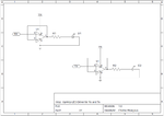
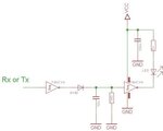
Another solution I came across is using a dual opamp like LM358N for RX/TX LED.
The schematic was posted on StackExchange:

I am really interested in implementing this method. I have the parts already. I want to read the sensor data with an Arduino Uno. The sensor uses RS232. I convert it via max3232 to Arduino. I want to see the activity via LED. Unfortunately I don't have my electronic devices and parts with me at the moment to test it and I am under pressure to see whether this works or not? I have seen at least one person reported that his LEDs remained on all the time using this method. But his UART voltage levels were 1.8V. Mine is 5V. Don't know whether it is relevant or not.
Also I would like to know how to stretch the pulse of the LED very simply? Can I use a capacitor in parallel to LED? I am transferring at 100K baudrates. I don't really care too much about the blinking. I just want to know something is happening! Staying on for 0.5 ~ 1 s or blinking 0.1s are fine ( or something in between ).
I dont have LD358D LT Spice model and various op amp models are giving me strange results!!! from staying on or oscillating between 25 and 28 mA at LED. I have already knocked myself out :fight::bang: and I'd be very grateful if you amazing people at EDABOARD could reach out to me.
Sincerely,
:thumbsup::thumbsup::thumbsup:
I am new to electronics. :roll:
I have already tried my best to do a thorough research on how to implement LED to see RX/TX activity.
The simplest solution was to connect LEDs and resistors in series to the RX/TX lines. Problem is that it could draws too much current and cause problems.
Another method I found was using various kinds of transistors like PNP or JFET to drive it. I have the parts but I haven't tried using them.
Another solution I came across is using a dual opamp like LM358N for RX/TX LED.
The schematic was posted on StackExchange:

I am really interested in implementing this method. I have the parts already. I want to read the sensor data with an Arduino Uno. The sensor uses RS232. I convert it via max3232 to Arduino. I want to see the activity via LED. Unfortunately I don't have my electronic devices and parts with me at the moment to test it and I am under pressure to see whether this works or not? I have seen at least one person reported that his LEDs remained on all the time using this method. But his UART voltage levels were 1.8V. Mine is 5V. Don't know whether it is relevant or not.
Also I would like to know how to stretch the pulse of the LED very simply? Can I use a capacitor in parallel to LED? I am transferring at 100K baudrates. I don't really care too much about the blinking. I just want to know something is happening! Staying on for 0.5 ~ 1 s or blinking 0.1s are fine ( or something in between ).
I dont have LD358D LT Spice model and various op amp models are giving me strange results!!! from staying on or oscillating between 25 and 28 mA at LED. I have already knocked myself out :fight::bang: and I'd be very grateful if you amazing people at EDABOARD could reach out to me.
Sincerely,
:thumbsup::thumbsup::thumbsup:
Last edited by a moderator:


