Continue to Site

Welcome to EDAboard.com

Welcome to our site! EDAboard.com is an international Electronics Discussion Forum focused on EDA software, circuits, schematics, books, theory, papers, asic, pld, 8051, DSP, Network, RF, Analog Design, PCB, Service Manuals... and a whole lot more! To participate you need to register. Registration is free. Click here to register now.

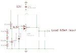
Opamp buffer with 400nF output capacitance going unstable?

Status
Not open for further replies.
T

treez

Guest
Newbie level 1

Attachments

  • 8v3 regulator.jpg
    8v3 regulator.jpg
    95.6 KB · Views: 234

I would not expect any op amp to be very happy about
that kind of load. You have a dual problem, the voltage
regulation (esp. load rejection) wants no resistance but
the stability wants a zero to compensate the "load pole"
(often a resistor between the output and capacitance,
with feedback taken from the op amp output (which would
ruin load rejection). It's possible that you could take the
DC feedback from the filter node (by resistor) and the AC
from the output (via capacitor) summing these into the
(-) input.

You might find capacitive-load drive application figures
which also address wide DC load ranges, but I've only
seen the resistor-in-series trick shown in old-timey
op amp app notes (back when vendors cared to go big
on design-in support).
 
  • Like
Reactions: treez

    T

    Points: 2
    Helpful Answer Positive Rating
Hi,

Yes there is a good chance that will happen.
It is a good idea to add some extra resistance on the output, but you should place the feedback connection right at the output of the OpAmp. To me it looks like it is placed at the capacitors.
Putting it there, you will properly make it more unstable. Having the feedback at the output gives you an additional pole in the feedback loop (beta), that will hopefully compensate enough.
 
  • Like
Reactions: treez

    T

    Points: 2
    Helpful Answer Positive Rating
See this document for many strategies to compensate for C loads. The "In-Loop Compensation" is nice as it adds no error (this is what dick was describing).
https://www.analog.com/en/analog-dialogue/articles/ask-the-applications-engineer-25.html

There are also opamps designed for high C loads including 'unlimited'. See LM7321 as one example.

Finally why use an opamp instead of regulator? I don't get the impression you need source/sink capability.
 
  • Like
Reactions: treez

    T

    Points: 2
    Helpful Answer Positive Rating
Thanks, actually there is some requirement for the opamp to sink current some of the time. 15mA was just an average figure.
What would you say is the maximum capacitive load allowable for an opamp buffer with MIC6211? (ie, the maximum capacitance allowable in the configuration as in the top post, with the feedback being taken from the "wrong" side of R172, as it is there)
Thanks asdf ill look at the article.
In the meantime would you say taking the feedback directly from the opamp output and leaving the 4R7 in there is the best way for now?

I have it like in the top post but with 200nF at the moment on the prototype, and its not oscillating.
 
Last edited by a moderator:

Hi,

An Opamp is not designed to drive that huge capacitive loads. Thus one has to expect problems.

Thus - at least for me - there are two obvious solutions:
* reduce capacitive load, or
* use regulators that are designed to drive high capacitive load ( voltage regulator, voltage reference...)

Another question is:
* Does your amp need to source AND sink current?

Klaus
 
  • Like
Reactions: treez

    T

    Points: 2
    Helpful Answer Positive Rating
Voltage buffers make sense when e.g. deriving multiple reference voltages from a central high precision reference. I'm often using mentioned LM7321 in this place.

Alternatively, there are different ways to compensate a general purpose OP for stable operation with a capacitive load. You should always check phase margin and/or buffer output impedance to verify that the design is stable. There's a certain risk to set up an oscillator with low level (< 100 mV) output magnitude.

As a side remark, voltage regulators basically suffer from the same problem as OPs and are not necessarily stable with arbitrary capacitive loads, e.g. those exposing too low ESR. You also need to check the stability range and load transient behavior.
 
  • Like
Reactions: treez

    T

    Points: 2
    Helpful Answer Positive Rating
Among the various C load compensation schemes your R scheme is about the simplest. The reference I linked has some equations to verify stability for your R scheme (which apply if the C load is well known).

Again I like the "In-Loop Compensation" since it offers a solution to both stability and DC accuracy and only adds 2 components.

There are some source/sink regulators out there too:
https://www.analog.com/en/products/lt1118.html
 

Regardless of what compensation scheme you choose, hopefully you have (or can borrow) a "Bode Box" to check the phase/gain margin.
 

Thanks, I will read about “in loop compensation” etc, it sounds good.
Today I actually addressed our contractor, and tried to talk him out of the circuit of the top post. However, also, I actually increased the capacitance to 570nF total and it still didn’t oscillate.
The opamp output current is as attached. As can be seen, it is mostly sourcing current, with a bit of current sinking.

...the contractor is laughing his head off at me...telling me i can increase the capacitance to 2uF and it still wont oscillate.
 

Attachments

  • Opamp output current.jpg
    Opamp output current.jpg
    67.1 KB · Views: 141
Last edited by a moderator:

You can handle 'a bit of sinking' with just a pull down.
 
  • Like
Reactions: treez

    T

    Points: 2
    Helpful Answer Positive Rating
Just to note, I’ve just actually wired in 51.7uF of capacitance in parallel with C2, and its still not gone unstable. (11 pieces of 4u7, 0805, 16v, X7R).

- - - Updated - - -

Also, I’ve then removed all the capacitors C111, C12, C1 and C2 from the schem in the top post, (plus removed the 51.7uF) and placed just 10nF, 0603, 50V, X7R there, and its still stable.
 

The 4.7R may be doing its job then. You could short its output and watch it recover - a simple step response test to get a sense of stability.


I'll say that this isn't theoretical. I've personally overloaded an opamp and seen it oscillate before.
 
  • Like
Reactions: treez

    T

    Points: 2
    Helpful Answer Positive Rating
With sufficient load capacitance and a respective loop bandwidth far below OP GBW, the circuit will be at least marginal stable and not oscillate. Phase margin is nevertheless low, resulting in an output impedance peak somewhere in the lower kHz range. It may be unwanted if you expect load transients.

A simple method to reduce the output impedance peak is to add real or artificial ESR to the load capacitance.
 
  • Like
Reactions: treez

    T

    Points: 2
    Helpful Answer Positive Rating
Thanks, yes I believe there is a real threat of instability here. Please could you check if the following would be unstable? (schematic attached) I have used “out of loop compensation”, as given on page 20 of the following article, kindly provided by asdf44….

Opamp stability document:
https://www.analog.com/media/en/ana...umber-2/articles/volume31-number2.pdf#page=19

....This just puts a compensation resistor in between opamp output and load capacitor (as many above kindly described).

The opamp output pole from the 200nF capacitor alone (no 4r7) would be 1/(2*pi*RL*CL)
Where RL = 976ohms (load on opamp output)
This pole is at 815Hz.

Adding the 4R7 compensation resistor adds a zero. According to page 20, this zero is at 6950 Hz.

This zero must be at least a decade in frequency below the closed loop bandwidth of the opamp circuit without the 4R7 compensation resistor. (ie just the 200nF load capacitor). –To find this bandwidth, the MIC6211 datasheet is used….and the pole at 815Hz is where the gain of 82dB can be said to fall off at 40dB/decade.
This line joins the 0dB axis at 815Hz/ [10^(-82/40)] = 91440 Hz

…this is at least a decade above 815Hz, therefore the 4R7 compensation resistor added in the attached will stabilise this opamp.
Would you agree?

Clearly there is something wrong here because it calculates that even a 1 milliOhm compensation resistor would give stability.
i think the zero frequency calculation of page 20 is wrong. (i also noticed that the schem on the RHS of page 20 is wrong, it has feedback going into the non-inverting input)

MIC6211 opamp datasheet
https://ww1.microchip.com/downloads/en/DeviceDoc/mic6211.pdf
 

Attachments

  • Opamp with output capacitance_1.jpg
    Opamp with output capacitance_1.jpg
    135.4 KB · Views: 127
Last edited by a moderator:

Hi,
Why don't you a HF feedback via capacitor from Opamp output and DC feedback from the big capacitors?

Klaus
 
  • Like
Reactions: treez

    T

    Points: 2
    Helpful Answer Positive Rating
Thanks, though do you think there is any chance of this circuit going unstable?......all output capacitors now removed.
 

Attachments

  • 8V3 regulator.jpg
    8V3 regulator.jpg
    90.4 KB · Views: 145

Aswell as post #17 above, please advise on this one here....

Do you believe the attached would also be unstable?, since really, the opamp will “see” that 100n output capacitance (C3), albeit that it will appear less due to the beta of the transistor.
The 2k7 R5 is needed because the load actually sources back for short intervals, as the “load waveform” shows.

MIC6211 opamp datasheet
https://ww1.microchip.com/downloads/en/DeviceDoc/mic6211.pdf
 

Attachments

  • Load waveform.jpg
    Load waveform.jpg
    64.4 KB · Views: 131
  • 8V3 regulator_1.jpg
    8V3 regulator_1.jpg
    81.4 KB · Views: 157

Hi,

I assume the BJT does not help.

You've got several hints on how to improve the circuit stability ... did you read the posts?

Klaus
 
  • Like
Reactions: treez

    T

    Points: 2
    Helpful Answer Positive Rating
Thanks, yes, Thanks for them, but we dont have money for a pcb respin...and so are trying to wangle what we have.
 

Status
Not open for further replies.

Part and Inventory Search

Welcome to EDABoard.com

Sponsor

Back
Top