Continue to Site

Welcome to EDAboard.com

Welcome to our site! EDAboard.com is an international Electronics Discussion Forum focused on EDA software, circuits, schematics, books, theory, papers, asic, pld, 8051, DSP, Network, RF, Analog Design, PCB, Service Manuals... and a whole lot more! To participate you need to register. Registration is free. Click here to register now.

Op-amps that have the fixed trip points are either Tripped by voltage or current?

Status
Not open for further replies.
How do you know which Polarity has the Hysteresis? it is always the negative polarity that has the hysteresis?

If a comparator or op amp has hysteresis, how would a tech know the hysteresis is not working? when testing the inputs and outputs?

- - - Updated - - -

Bench Check Tests I do when testing comparators in the circuits , I'm guessing there is different types of Hysteresis

Hysteresis TYPE#1
1.) Raise the Positive voltage up until you FIND the threshold switching point, the output switches states to a HIGH
2.) Lower the Positive voltage down until you FIND the threshold switching point, the output switches state to a LOW

The Positive voltage going up will have a different threshold switching point voltage and current than the positive voltage going down
You turn the trim pot up until you find the threshold switching point, you turn the trim pot down until you find the threshold switching point
This will change the output state from HIGH to LOW
But the Positive voltage going up will have a different threshold hold switching point value than than the positive voltage going down

The positive voltage going UP will switch at +5 volts
But the Positive voltage going Down will switch at 1 volt

How does the Hysteresis do that?

I would think it would switch at +5 volts going UP and going DOWN , not at two different voltages

Why is that and how does the hysteresis do this?

It seems that the Positive voltage going UP doesn't have the Hysteresis ONLY the Positive voltage going Down?

What Hysteresis is this type called ? is this the positive feedback one?

Hysteresis TYPE#2
1.) Raise the Positive voltage up until you FIND the threshold switching point, the output switches states to a HIGH
2.) Flip the Polarity to a Negative voltage ( - ) and raise the voltage until you FIND the threshold switching point, the output switches states to a HIGH

It seems like there is Two different Hysteresis , one for each Polarity?

Because the Positive voltage will switch at + 5 volts
and the Negative voltage ( - ) will switch at -3 volts , I would think it would be at - 5 volts

But this output only goes to a HIGH state not a low state , either polarity positive or negative

What Hysteresis is this type called ? is this the positive feedback one?
 

Please I need help with this to understand it for my job at work , you do help me out a lot thanks for the help

a different trip point depending on polarity will probably be due to how they have set the hysteresis
Yes, that is what is happening, but how do they do this?

When you switch the Polarity switch to a ( - ) , it will cause the output to go LOW , until you raise the (-) polarity until you cross the threshold trip point which will switch the output to a HIGH

When you switch the Polarity switch to a ( + ) , it will cause the output to go LOW , until you raise the (+) polarity until you cross the threshold trip point which will switch the output to a HIGH

The output starts off in the LOW state , until you cross the threshold

Hysteresis Type#1
the Hysteresis for the Positive and Negative Polarity have different Crossing thresholds

The Positive rising has a different rising trip point than the Negative Rising trip point

( When you Flip the Polarity switch it causes the output to switch to a LOW state)

This Hysteresis type#1 we never do a falling trip point , we only switch the polarity and so Rising Trip Point

Hysteresis just means that the rising trip point and the falling trip point are different
YES , That is what I am getting, But how do they set or what sets the rising trip point and what sets the falling trip point? they both have different voltages

Hysteresis Type#2
The Hysteresis for the Positive Rising has a different voltage than the Positive Falling trip point
 

You are making a distinction where there is no difference. There are not two essential different kinds of hysteresis. There is only one hysteresis, although it may show up in many different places. But it is really simple. It is just the result of feedback. When a threshold has been reached, something changes as result of reaching that threshold. In the case of a comparator, the "something" that changes is the output of the comparator. Now if the circuit takes that output and feeds it back in some way to the input, that can change the comparator threshold so that it now must cross a different threshold before the output will switch back to what it was before. But you say you need to know this for work. What are you trying to do? Design a circuit with hysteresis? Or fix a circuit that is not working properly? Or do you just like asking questions?
 

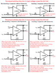
I copied parts of the datasheet of the LM339 quad comparator IC and posted it as a reply to your same questions on another website forum:
 

Attachments

  • comparator and hysteresis.png
    comparator and hysteresis.png
    59.9 KB · Views: 72

The Positive-Going Threshold and the Negative-Going Threshold have different values
At work they reverse the Polarity on the Vin input
1.) Positive-Going threshold for the Positive Polarity, cause output to go HIGH
Postive voltage on Vin input, Move the trim pot CW until the output is HIGH
2.) SWITCH the polarity to Vin input to a Negative voltage
3.) Negative-Going Threshold for the Negative Polarity, causes output to go HIGH also
Negative voltage on Vin input, Move the trim pot CW ( not CCW ) until the output is HIGH

They other way they do it at work is
The Positive-Going Threshold and the Negative-Going Threshold have different values
They keep the Polarity Positive on the Vin Input
1.) Move the trim pot CW until the Positive-Going Threshold switches the output to a HIGH
2.) Move the trim pot CCW until the Negative-Going Threshold switches the output to a LOW

Can't you see the difference between the Two examples?

The Ones in the datasheets are different also cause they Flip the non-inverting input or the inverting input to be Vin input

Why do they use Hysteresis?

I have seen transistors used as a switch with Hysteresis, but what for? so the input doesn't cause False switching from noise?
 

At work they reverse the Polarity on the Vin input
1.) Positive-Going threshold for the Positive Polarity, cause output to go HIGH
Then the comparator circuit is non-inverting as I showed.

Postive voltage on Vin input, Move the trim pot CW until the output is HIGH
You did not post the schematic so we do not know where the trimpot is connected.

2.) SWITCH the polarity to Vin input to a Negative voltage
You did not post the schematic so we do not see a switch.

3.) Negative-Going Threshold for the Negative Polarity, causes output to go HIGH also
Then the comparator circuit is inverting as I showed.

Negative voltage on Vin input, Move the trim pot CW ( not CCW ) until the output is HIGH
No schematic from you again.

They other way they do it at work is
The Positive-Going Threshold and the Negative-Going Threshold have different values
Then the voltage reference is not at half the supply voltage.

They keep the Polarity Positive on the Vin Input
1.) Move the trim pot CW until the Positive-Going Threshold switches the output to a HIGH
2.) Move the trim pot CCW until the Negative-Going Threshold switches the output to a LOW
A comparator does not have one Vin input. Instead it has (+) input and a (-) input.
You are talking about a non-inverting comparator so the Vin from the trimpot is its (+) input and the (-) input has the voltage reference.

The Ones in the datasheets are different also cause they Flip the non-inverting input or the inverting input to be Vin input
I showed (+) input as the input then the comparator circuit is non-inverting and I showed the (-) input as the input then the comparator circuit is inverting.

Why do they use Hysteresis?
We asked you to look it up. It prevents noise on the input from flipping the output and it speeds up the switching.

I have seen transistors used as a switch with Hysteresis, but what for? so the input doesn't cause False switching from noise?
Yes, and it speeds up the switching.
 

Ok thanks for the info and clearing it up

So when I flip the polarity switch on the text fixture at work , it must switch the Vin input to either Non inverting input or an inverting input?

Sorry I don't have the schematic to the Text fixture at my work so I don't know what's inside of it

I thought you put Into a negative or positive voltage on either Non inverting or inverting inputs on an op amp

Input an Positive voltage on the Vin of an Non- inverting input would output a HIGH

Input an Negative voltage on the Vin of an Non-inverting input would output a LOW

I just flip the switch on the test fixture at work to switch the polaritys on the Vin , I don't change the Vin from going to Non-Invertering to an Inverting input on a op amp

- - - Updated - - -

It prevents noise on the input from flipping the output and it speeds up the switching.

How does it speed up the switching?

I do have to Bench check at work the Switching time of a comparator and op amps

Maybe there is a problem with the Hysteresis causing the switching timing problems?
 

How does it speed up the switching?
Hysteresis is positive feedback. A resistor from the output to the (+) input.
When a positive-going input signal slowly passes the threshold voltage then the output begins to go positive and the feedback resistor makes the (+) input more positive that makes the output go more positive and the feedback resistor makes the (+) input even more positive, etc.
When a negative-going input signal slowly passes the threshold voltage then the output begins to go negative and the feedback resistor makes ..... as before.

I don't get how that Speeds up the switching

Where is it speeding up the switching at?

- - - Updated - - -

Are you trying to say that when you put a 1 volt on the input and output is 1 volt, it feeds back the 1 volt so now you have 2 volts on the input and the output is 2 volts and that is feed back to the input and how you have 4 volts on the input

The Hysteresis feedback path doubles the input each time it outputs a voltage? because it feedbacks the outputs voltage on the inputs voltage, doubling or adding to the inputs voltage which speeds up the timing or switching?
 

A comparator IC has a voltage gain of about 200,000 (1/5th of 1 million) times. So when the input is 0.001V then the output will try to be 200V.
Positive feedback from adding hysteresis causes the output to force the input voltage higher than the input signal level which causes a very fast "snap" action even when the input signal is very slow.

Hysteresis action is the same as Schmitt Trigger action. Look up both terms on Google.
 

Status
Not open for further replies.

Part and Inventory Search

Welcome to EDABoard.com

Sponsor

Back
Top