Welcome to our site! EDAboard.com is an international Electronics Discussion Forum focused on EDA software, circuits, schematics, books, theory, papers, asic, pld, 8051, DSP, Network, RF, Analog Design, PCB, Service Manuals... and a whole lot more! To participate you need to register. Registration is free. Click here to register now.
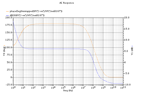
attached below the gain curve of certain Opamp
i dont have schematic design , i want to understand how come to have -ve slope gain while phase is increasing ?
is it RHP zero ?
can any body explain to me the low freq gain effect in the graph (0- 10Hz)
Looking how looks the plot increasing frequency, it seems that:
(1) at dc (freq=0) gain is quite high and phase is 180 deg (inverting amplifier)
(2) al some very very low frequency (not seen in the plot) there is a real pole; gain starts to drop at 20 dB/decade an phase decreases towards +90 deg
(3) there is a real zero at about 4 Hz (in LHP) that stops the drop of gain and raises phase up to 180 deg
(4) there is a real pole at about 70 MHz that starts a drop in amplitude and produces a total lag in phase of 90 deg
(5) there is a real zero in RHP at about 400 MHz that stops drop in amplitude and lags the phase 90 deg more
At low frequencies (between 1 and 10 Hz), the negative slope in gain is produced by the pole (2), and the increasing phase by the zero (3).
Regards
This site uses cookies to help personalise content, tailor your experience and to keep you logged in if you register.
By continuing to use this site, you are consenting to our use of cookies.