Salvador12
Full Member level 4

I will make a setup and i'm almost sure how it should work, but I want to check. Sorry for my previous threads being somewhat confusing.
So the idea is this. I have a high frequency generating coil part of a circuit and I need that high frequency to be converted down to mains frequency.
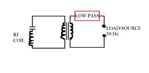
I will make the high frequency coil generate PWM wave into the primary of a transformer with a capacitor in series. So the primary loop as can be seen in the drawing is a series LC.
the secondary contains a low pass filter.
If my understanding is correct and please do correct it if necessary two things should happen
1) Power should be able to flow from the high frequency side through the transformer/filter into any load on the low frequency side
2) Power from the low frequency side (if load become source) cannot flow back into the high frequency side , at least not by any large margin because the frequency is low and the high frequency side has low capacitance capacitor + series LC resonance would present a very high reactance to the low frequency
Therefore due to differences in frequency power can only flow from left to right in the drawing and not vice versa or it can flow from high frequency side to low frequency side but not back, correct?
Another question is this, given the primary side and secondary side work on high frequency, the transformer therefore can also be a high frequency transformer , but as a high frequency transformer its turns ratio would be different than a typical mains transformer, yet the secondary side of the transformer still has mains 50 Hz across it, how would these factors work, because as far as I'm aware a low pass filter does permit low frequency power flow both ways right? It's only the high frequency that is cut off, so the low frequency power would be able to reach the transformer secondary ?
But if I'm right given the transformer primary works with high frequency and would present an almost open circuit for low frequency it would make the transformer secondary a very high inductance load for the 50Hz current so that would block the low frequency power from passing through the transformer. One thing i'm not sure is how would the low frequency power affect the secondary coil given it would have a lower turns ratio than a mains transformer and therefore would heat up with 50Hz current passing through it?


