johnny78
Full Member level 5

- Joined
- Jun 28, 2017
- Messages
- 270
- Helped
- 1
- Reputation
- 2
- Reaction score
- 5
- Trophy points
- 1,298
- Activity points
- 3,469
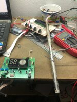
hi Guys
i was asked to fix this device for some friends but i couldnt understand how it works of find any information about it
the MCU is P87LPC764FN which i downloaded the datasheet & there is no analog input
the sensor reads the water level 4 steps & the temp of water using 4 wires & im not familiar with this kind of connection
the four wires enters 74hc04 hex inverter which i will draw the input schematic
the sensor has 4 wires which i cant find what is it for
https://www.aliexpress.com/i/1005001734767504.html
here is the controller
any help will be great
Johnny

https://www.aliexpress.com/item/1005003752897979.html
i was asked to fix this device for some friends but i couldnt understand how it works of find any information about it
the MCU is P87LPC764FN which i downloaded the datasheet & there is no analog input
the sensor reads the water level 4 steps & the temp of water using 4 wires & im not familiar with this kind of connection
the four wires enters 74hc04 hex inverter which i will draw the input schematic
the sensor has 4 wires which i cant find what is it for
https://www.aliexpress.com/i/1005001734767504.html
here is the controller
any help will be great
Johnny
--- Updated ---
here is the sensorhi Guys
i was asked to fix this device for some friends but i couldnt understand how it works of find any information about it
the MCU is P87LPC764FN which i downloaded the datasheet & there is no analog input
the sensor reads the water level 4 steps & the temp of water using 4 wires & im not familiar with this kind of connection
the four wires enters 74hc04 hex inverter which i will draw the input schematic
the sensor has 4 wires which i cant find what is it for
https://www.aliexpress.com/i/1005001734767504.html
here is the controller
any help will be great
Johnny
https://www.aliexpress.com/item/1005003752897979.html
Attachments
Last edited:
