Continue to Site

Welcome to EDAboard.com

Welcome to our site! EDAboard.com is an international Electronics Discussion Forum focused on EDA software, circuits, schematics, books, theory, papers, asic, pld, 8051, DSP, Network, RF, Analog Design, PCB, Service Manuals... and a whole lot more! To participate you need to register. Registration is free. Click here to register now.

Offline flyback failing HiPot test.

cupoftea

Advanced Member level 5
Joined
Jun 13, 2021
Messages
2,930
Helped
59
Reputation
118
Reaction score
134
Trophy points
63
Activity points
15,518
Hi,
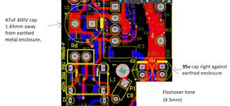
We have an offline , isolated 24W Flyback in an earthed
metal enclosure.
We use TO220 Plastic FET in primary and TO220 plastic
diode at secondary. They are both screwed to the same metal heatsink.
(with no insulation pad)
Then when we apply our 4kVrms (between L+N and output for 2 seconds, it is failing.
Do you believe we need an insulation pad?

When i say its failing, it doesnt indicate failure, but we can hear fizzling at 4kV indicative of breakdown.
The 0-3mA current meter reads no current.
 
OK, so it's failing but not failing. What's the question?
Oh, pad or no pad. Have you any particular reason to
think it's the power devices to heat slab? Emissions
microscopy? Stethoscope (4kV, guess your basic metal
automotive one is right out)?

Of course cut-and-try probably costs you a shilling
and an hour to bodge it up. Better than guessing I
imagine.
 
If you can hear 'fizzling' try looking at it in total darkness, you should be able to see a corona around the arcing point. Is it possible you see no current because it isn't passing through the equipment but arcing to something else nearby, a table top for example.

Brian.
 
Theres also an insulated earth wire that runs from earth terminal on the mains connector, and touches mains L and N solder pads, and then "worms" on and touches Vout pos and neg pads....i just wonder if this approx 3mm thick earth wire is flashing through its insulation?

Thanks yes, we are looking for the sparks, and have it on 4kv rms (50Hz) whilst we do this...i just wonder at what point we have to stop because the 4kV will surely eventually damage many components.?

We have an X2 cap right next to a metal earth enclosure wall.....and that was flashing through to this enclosure (we saw the sparks)....and then the earthed enclosure also goes round to the secondary side, where there are 35V electro caps up against it....so maybe there is a multi-path flashover happening here?

We put tape over the wall near the x2 cap, and we still hear fizzling. The trouble is we have to part-disassemble it to look for sparks (so we can see inside), and then its not the real situation.

We also have a 24V secondary side via just 0.7mm away from the earthed enclosure wall, where the wall comes down to the PCB.
The primary HVDC bus electro cap has its circumference coming to within 1.5mm of the earthed enclosure.

We have a Y2 cap from primary HVDC+ to Earth.
We also have a Y1 cap across the flyback transformer (HVDC+ to secondary ground)

We also have a VOM617A-4T opto which is only rated 3.75kv rms which does secondary to primary feedback. (and we are testing to 4kV rms)
The contractor just says that "it will be OK"....its not that far off in voltage 3.75kv to 4kv.

We are testing from L+N to output at 4kv rms.
We are testing from L+N to earth with 2kV rms.

Sometimes we see flashover but it doesnt fail on the hipot tester failure indicator..but sometimes it does fail.

The flyback transformer is rated 4kV/5mA/2Seconds....but we have been slamming it with continuous 4kV for long periods as we look for the sparks...do you believe now that our transformer is now totally ruined in terms of its isolation capability?
If a flyback transformer is rated for 4kV/5mA/2 seconds, then what happens to it if it is exposed to 4kV for 60 seconds?

Its a flyback that got crammed into an existent enclosure.
 
Last edited:
Thanks, do you know, If a flyback transformer is rated for 4kV/5mA/2 seconds, then what is likely to happen to it if it is exposed to 4kV for 5 seconds?
Is there likely to be some insulation degradation.?

Also, if a product fizzles, and even sparks on a 4kv rms hipot test, but does not trip the "fail" inducator, and the discharge current meter doesnt visibly go up, then is that a fail or pass?
...When we get fizzling, (but no failure indication) whats happening is that we just repeatedly apply 4kv rms to the product, to see if it eventually fails or not....but then surely any product is eventually going to fail if 4kV is repeatedly applied?

We are using an FT4 insulation tester
 
Last edited:
I think you have to step back from the product and look more generally at what makes the sound. The 'fizzling' can be caused by direct arcing, although this tends to be quite loud, or by ionization into the atmosphere, particularly from sharp points such as wires/pins protruding from solder joints. Don't just think of it in terms of spacing, the shape of discharge points plays a large part in corona generation. For example, if you find a particular through hole solder joint is the culprit, make sure the wire is folded down prior to soldering and the problem may be fixed.

You also have to consider how the flash tester measures current, if it is done on the return (low voltage) probe and your 4KV is put on the other probe, it will fail to measure discharge outside its own loop. The current flowing in a corona discharge closely follows the sound it makes, almost random, so filtering in the tester may also remove some or all of the measurement.

I doubt if the test is done in a dry environment whether the duration of the flash test makes much difference, if it can withhold a high voltage it can probably do so almost indefinitely. The voltage stresses the insulation but shouldn't gradually degrade it.

I should point out my qualification in this - I failed the BS flash test inspection, but only because the floor mat at the test bench wasn't thick enough!

Brian.
 
Thanks, indeed i am seeing flashover from the square pad of the electro cap to the earth screw. (during 4kv hipot from pri-sec)
This is 4.5mm along the PCB. Its a surprise to see it jump so far. I actually desoldered the cap to stop the arc, but it still happens from the square
pad of the cap.

Also, the FT4 hipot tester has three settings...
1..."Burn"....simply keeps applying test voltage as long as it can
2..."trip off as soon as any flashover/breakdown whatsoever"
3..."trip off" but only when the steady discharge current through the isolation barrier rises above 3mA. (can be set from 0.1 to 3mA trip level)

Now, would'st we be correct in saying that the 3rd setting above is the one that all of the safety standards refer to?
 

Attachments

  • Hipot_PCB.png
    Hipot_PCB.png
    144.2 KB · Views: 49
  • Hipot_PCB1.png
    Hipot_PCB1.png
    185 KB · Views: 47
Last edited:
I would guess a "trip off" means a failure.

I'm surprised C1 isn't arcing but then it doesn't have a pointed corner. Discharges prefer point and spikes, it concentrates the charge at that point.

You could do a 'dirty' fix on a bare PCB before assembly, use a small circular saw (Dremel etc.) to cut a slot between the screw pad and the near corner of C2 pad to provide an isolation gap. If it fixes the problem and this is an ongoing product you could add it to the fabrication files and have it included in board production.

Brian.
 
This 1k/mm is due to creepage effects and why an air gap rated at 3kV/mm is routed in the PCB to PE gnd and between lines. Yours needs a re-route.

I chose to test with a slow ramp of HVDC 10% higher, sustained for 1s after caps charge up and trip/fail if more than 100 uA with an R current limit for arcs.

This is only a CM Hipot test.
 
Thanks, this PCB sits in an earthed metal enclosure, which is not accessible to human hands..because its inside another metal full enclosure.
As such, since the boards still work following this flashover, i presume that we are ok to pass this off?
The customer says for the application that the 4.5mm was fine.
Nobody could possible touch it.
--- Updated ---

Also, primary has a plastic TO220 FET screwed to the heatsink, and secondary has a TO220 plastic diode screwed to the same heatsink....so the distance between the conductors in those TO220's is probably only effectively some 3mm....would you say this is a concern? (because during the 4kv pri-sec test, the earthed metal enclosure is totally floating.
 
Last edited:
I wonder which standard requires 4 kV test voltage? Is it more than 230/400 V, CAT. II, reinforced isolation?

As stated, partial discharge without noticeable current is no breakdown. Test apparently passed. It surely indicates, that the insulation won't permantly stand 4 kV working voltage. Of course clearance and creepage should confirm with requirements, didn't hear yet about violations.
 
classic - 4kV ac is over 6kV pk, easily over the 1kV/mm classically used
Thanks, yes you are right, but what is puzzling is that this PCB is replacing a similar one which had clearance of just 4.8mm between the pri and sec pads of the feedback opto, (and no slot)...and also multiple areas between 4.8mm and 5.3mm across the isol barrier...so why that one doesnt also fail we dont yet know...because it too is exposed to the 4kv test.

I think where the "bad" board is failing, is where we have capacitors very near to the (totally surrounding) metal enclosure, and the high voltage is just using this enclosure as a conduit between components at either side of the isol barrier. But we placed transformer tape to insulate such components from the metal enclosure and the flashover still happens.
 
Adjust the test to 3200Vac, and check with a scope the output waveform - many of the smaller crappier units react badly with Y caps and cause excessive peaking of the mains waveform, giving a very high peak to rms figure, i.e. much higher than 1.414
 
Thanks, we have 100:1 probes, but they are only good for up to 3000Vrms, since we are using a Rigol DS1054 scope..
Do you know how we may probe it?

We are suing the Megger FT4 flash tester..
 
Qu1....Is HiPot Test for power supplies necessary to prevent data corruption?
Hi, We have an offline , isolated 25w Flyback SMPS in an earthed metal enclosure. This flyback
also acts as a "daisy chain" terminal for passing on a CAN bus wire pair.
(it has a CAN bus connecter with termination
resistor)
The CAN bus goes to other equipment along with the 24V output of this isolated SMPS.
The hipot test is done at 4kVrms/2 seconds/no breakover.

This seems a rather high voltage for a hipot test.

Though we are told that it is necessary to ensure that the data doesn't get corrupted.
I mean, ok, why not do the hipot test at 5kv then?..or 6kV?...and protect the data even more?
...and add in shielded cable for the data whilst we are about it?....etc etc

I mean, Even if the data does get corrupted during a typical mains transient (what do they last, some 50us max?),
the processors all have error routines to handle such things. The equipment we have here isn't
medical equipment.

So do you agree that 4kV hipot tests are not needed for safety, or for insulation withstand testing?...but to
ensure that data doesnt get corrupted?

Also,
Qu2 Y capacitor location for Conducted immunity?...for conducted EMC?
Hi, As you know , in an offline SMPS supplied by L,N & E, the Y capacitors would go from
L and N to earth. They can be placed either upstream or downstream of the
common mode choke. Is the following right?..
(please assume that in all cases there is alreasy a Y capacitor across the isolation transformer, from quiet node(primary) to
quiet node(secondary)
1)..Placing the Y capacitors upstream of the common mode choke is best to give immunity of the SMPS (and whatever it supplies)
2)...Placing the Y capacitors downstream of the SMPS is best to get a conducted EMC pass of the SMPS?
3)...If you only have room for one Y capacitor, then where would you place it?...presumably after the diode bridge to either
HVDC+ or HVDC-, because in that case, it would alternatively connect to L and N , every alternate 10ms?
 
Last edited:
Avoid sharp corners that raise E-field (kV/mm) , and use a string of axial components to make a 10:1 divider using resistive elements. Calibrate at low V. Good enuf for 50 Hz.

Use spark plug carbon wire as a probe to an R ladder to 10:1 probe for whatever you need. 1000:1 or 2000:1

1723292823477.png

1723292882659.png


Partial Discharge (PD) may corrupt data but pass leakage test. Pulse rate can be 1/minute to 1/sec to >=1/cycle then it's called corona discharge if in air. PD is only caused by contaminants in/on the dielectric insulator. Rise times are picoseconds unless filtered. Corona is a result of failure for dielectric withstanding. Since Corona is normally visible white/blue light, air temperatures are > 5000'K.

Normally porcelain bushings on grid poles are rated by impulse voltage. e.g. BIL200 = 200 kV impulse but can only handle 20 kVrms to 40 kVrms from creepage and might be 40 cm long. ie. ionization time (microsec.) increases withstanding voltage if pulse is 1~10us.

To make a pre-scaler divider, use carbon spark plug wire to an R ladder with YAGEO HHV series resistors 1/4 W coated with silicone on a wood base with less than 1pF stray capacitance per each resistor (1pF=300Meg @ 50Hz).
--- Updated ---

For a constant leakage current, the voltage drop is proportional to the impedance of every path in the loop until PD or ionization occurs.

So if one part of the path gets worse for leakage conductance, that puts more kV/mm stress on the rest of the insulation if that part did not change.

So do not overlook that.
--- Updated ---

Pls confirm your test.

Is it the 1.25/10us crest voltage waveform with 8/20us current if arc'd?
 
Last edited:
3....Floating copper on isolated SMPS PCB floats up to very high voltage during hipot test?
Hi,
Does any floating copper on a PCB float up to very high potential during the hipot test
from L+N to isolated output?
Eg we have a small bit of PCB which stands vertically in between our primary side NTC and electro cap in
order to stop the NTC burning the electro cap. It has a PTH pad which isn't connected to anything,
ie, its floating. Supposing the SMPS were hipot tested to 4kVrms from L+N to isolated output. Will this pad possibly
go to a potential of 5.65kv or more, in relation to the pads and tracks surrounding it?
 

LaTeX Commands Quick-Menu:

Part and Inventory Search

Welcome to EDABoard.com

Sponsor

Back
Top