Continue to Site

Welcome to EDAboard.com

Welcome to our site! EDAboard.com is an international Electronics Discussion Forum focused on EDA software, circuits, schematics, books, theory, papers, asic, pld, 8051, DSP, Network, RF, Analog Design, PCB, Service Manuals... and a whole lot more! To participate you need to register. Registration is free. Click here to register now.

Non isolated AC voltage sense

Status
Not open for further replies.

satiz

Member level 5
Member level 5
Joined
Jun 9, 2013
Messages
87
Helped
3
Reputation
6
Reaction score
3
Trophy points
1,288
Activity points
1,999
Hi There,

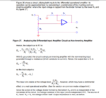
I am planning to using Differential amplifier for AC voltage sense . I want formula to find V2 in the attached circuit.
My aim is to find the differential amplifier output. To get that I want to calculate Differential mode voltage
Vd= [Non-inverting input] - [Inverting input]
I need formula to find Inverting terminal volt and non inverting terminal volt.
Please help me.

Differential amp.jpg


Thanks regards
Satiz
 

Hi,

Why do you say "differential"?
I see a "voltage divider* and a "non inverting Opamp circuit".

Klaus
 

Hi Klaus,

simplified one.jpg

Simplified circuit is attached for your reference.
 
Last edited:

Hi,

Two things represent the typical difference amplifier circuit:
* it contains 2 x 2 equal resistors
* and the most important: no input does reference to GND

Signals (or circuits) that reference to GND are single ended signals.
They are no difference signals, no relative signals, they are absolute signals.

Tell us your idea, why do you call it "difference amplifier".

Klaus

I agree with your point.

This is a TI reference design. they have mentioned as Differential amp and formula also matched with there given gain.

Here is the link for that. Please refer Non Isolated voltage sense section. (2.2.2)
https://www.ti.com/lit/ug/tiduby7a/tiduby7a.pdf


Below is easy reference
TI reference.PNG

- - - Updated - - -

Hi,

Two things represent the typical difference amplifier circuit:
* it contains 2 x 2 equal resistors
* and the most important: no input does reference to GND

Signals (or circuits) that reference to GND are single ended signals.
They are no difference signals, no relative signals, they are absolute signals.

Tell us your idea, why do you call it "difference amplifier".

Klaus


Please refer this circuit too
https://www.ti.com/lit/an/sboa092b/sboa092b.pdf

PDF page number 24.

Easy reference image
reference.PNG
 

Hi,

Now that things clear up.
You showed only one part out of two.
Each single part is single ended. Only two wired together make it to a differential input.

The amplifier is configured in differential mode and depending on the application and the input voltage range, the gain can
be configured.
But here I don't agree with the author. Not the amplifier is configured in differential mode (the both amplifiers work independently)
..but the ADC is configured in differential mode...the ADC has two inputs, an inverting input and a non inverting input....here is the "difference".

Klaus
 

you would normally have (2) large resistor strings, one going from + input to phase and the other - input to Neutral. then the low value feedback R and R to local 0v - this would be a true diff amp on the mains ...
 

I agree that differential voltage divider is the appropriate solution for most AC voltage measurement applications. There are cases where the measurement circuit ground is tied to one input voltage terminal. Then a single ended voltage divider as used in post #1 does the trick. The amplifier adds an offset voltage to achieve a bipolar range but doesn't involve a substract operation because input and output ground are identical. Respectively there's no CMRR figure.

The circuit in post #5 is referring to a difference amplifier, as probably noticed, the resistor ratio is adjusted for the 3.3k voltage divider output resistance. If I understand right, you don't know how to calculate the circuit gain. But that's rather trivial, two cascaded dividers and a non-inverting amplifier. I think it's more straightforward than referring to a modified difference amplifier calculation.
 
  • Like
Reactions: satiz

    satiz

    Points: 2
    Helpful Answer Positive Rating
I agree that differential voltage divider is the appropriate solution for most AC voltage measurement applications. There are cases where the measurement circuit ground is tied to one input voltage terminal. Then a single ended voltage divider as used in post #1 does the trick. The amplifier adds an offset voltage to achieve a bipolar range but doesn't involve a substract operation because input and output ground are identical. Respectively there's no CMRR figure.

The circuit in post #5 is referring to a difference amplifier, as probably noticed, the resistor ratio is adjusted for the 3.3k voltage divider output resistance. If I understand right, you don't know how to calculate the circuit gain. But that's rather trivial, two cascaded dividers and a non-inverting amplifier. I think it's more straightforward than referring to a modified difference amplifier calculation.

I calculated the gain using differential amplifier formula, Check the Image 1. CMRR is 114db. If this is Ideal opamp both the input terminals are virtually shorted. But I have doubt here to calculate non inverting terminal input voltage.
 

Hi,

But I have doubt here to calculate non inverting terminal input voltage.
With not connected HV input nodes:

GND - 3k3 - 8k2 -V- 14k2 - 2V5

=

GND - 11k5 -V- 14k2 - 2V5

-V- is the node for non inverting OPAMP input.

use the voltage divider formula

Klaus
 

Can anyone tell me, how can I add LTSPCIE .asc file here
 

Hi,

rename it as .txt and upload it as attachment.

CMRR is 114db.
Maybe in simulation with almost ideal devices, but not in reality.

Klaus
 

Here is the LT Spice file for reference
 

Attachments

  • Non-Inverting Opamp Voltage sense_2.txt
    2.3 KB · Views: 114

Status
Not open for further replies.

Similar threads

Part and Inventory Search

Welcome to EDABoard.com

Sponsor

Back
Top