Continue to Site

Welcome to EDAboard.com

Welcome to our site! EDAboard.com is an international Electronics Discussion Forum focused on EDA software, circuits, schematics, books, theory, papers, asic, pld, 8051, DSP, Network, RF, Analog Design, PCB, Service Manuals... and a whole lot more! To participate you need to register. Registration is free. Click here to register now.

Non-inverting amplifier - LM358N

Status
Not open for further replies.


You can't let inputs floating. Proper biasing is required.


So same problem. Who do I believe? Multisim or the thousands of example circuits?
Both.

The example circuits are DC coupled at the input, so they don't need biasing. However your circuit has an input coupling capacitor, so it needs DC biasing to work properly.
 

Who do I believe? Multisim or the thousands of example circuits?

While reading the whole thread from the beginning - my impression is: A combination of misunderstanding and lack of basic knowledge.
Just one recommendation to boylesg: Try not only to "believe" but to understand (instead of blaming a simulation program).
 

If move that resistor to the non-inverting input to GND then the positive signal doesn't clip, but that connection is not specified in the datasheet.
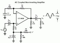
Generally speaking, a datasheet isn't primary intended to teach OP circuit design basics, although it still does to some extend.
In particular, I see a noninverting AC amplifier circuit in my LM358 datasheet, "specifying" the bias resistor. But in any case, most knowledge will been acquired by practical experience, including failure. It works!

 
  • Like
Reactions: tpetar

    tpetar

    Points: 2
    Helpful Answer Positive Rating


You can't let inputs floating. Proper biasing is required.


I found this tutorial which is a much more helpful in a practical sense: https://www.societyofrobots.com/robotforum/index.php?topic=9840.0

In it they have an ac coupled amplifier with a resistor to ground either side of the input capacitor.

I think I can see why. Because the audio signal either side of the capacitor is relative to different grounds - the, for example, ipod ground on one side and the opamp GND on the other. And they may or may not match exactly.

But surely that would not specifically result in the the positive side of the audio signal being cut off entirely and the negative side of the audio signal being amplified as expected? If the GNDs are different then I can see no logical reason why the negative part of the signal wouldn't also be distorted in some way.

This highly specific gross clipping in multisim must still be just a very confusing artefact of its failure to more closely match reality?
 
Last edited:

That circuit has a 1M resistor from the non-inverting inputs to a voltage generated by the 10k/6.8k divider. That is because it is running from a single supply so to amplify AC signals you need to set your virtual earth point above 0V.

Keith.

- - - Updated - - -

You can do the same thing with your amplifier - see attached.
 

Attachments

  • Simple LM356 amplifier.pdf
    17.1 KB · Views: 145

That circuit has a 1M resistor from the non-inverting inputs to a voltage generated by the 10k/6.8k divider. That is because it is running from a single supply so to amplify AC signals you need to set your virtual earth point above 0V.

Keith.

I understand about virtual earths when you are running from a single supply. It all makes logical sense to me.

But the way multisim is distorting the input signal because I don't have consistant ground potentials either side of the input capacitor does not make logical sense to me.

I understand that the results of doing this for real might be unpredictably random distortion. But what multisim is doing looks far from unpredictably random distortion.
 

The resistor on the capacitor's left side has a rather trivial purpose. It assures zero DC voltage before connecting the input source and avoids unpleasant click sounds when plugging it.

The waveform in your simulation is very near to real circuit behaviour except for one point. You would see an average output voltage of zero rather than negative halfwaves only. This is specific result of transient simulation's initial bias point and starting the input voltage with zero at t=0. If you run the simulation for a longer time, the average will slowly move upwards. By probing the OP output directly, you'll realize that it's clipping near the positive supply rail, which has to be expected due to LM358 input current polarity.

A lot to learn even from failed experiments.
 
  • Like
Reactions: tpetar

    tpetar

    Points: 2
    Helpful Answer Positive Rating
Bias Vs Without Bias

Dear boylesg,
Don't consider the theoretical circuit & simulation programs... Try to understand the real concept of biasing. Biasing is the most basic thing to understand analog electronics. we need to provide DC bias to the OPAMP input & the capacitor will not allow the DC to the Non-Inverting input. See the attachment the input is totally shifted above the ground level then you can not expect the output voltage to the Rail-Rail.

- - - Updated - - -

I repeat again(my personal opinion) i don't think multisim is a good simulation tool. It is acceptable for ideal OPAMP design but it is not efficiently using the spice model of the components.
we know LM358 is not a rail to rail output OPAMP. For 12V power supply the output will never reach >11v. But see the attachment[comparator], the output swing to -11.685v which is not possible for LM358...
Anyone accept this?

Regards
Udhay
 

Attachments

  • no bias.png
    no bias.png
    65.1 KB · Views: 113
  • with bias.png
    with bias.png
    65.4 KB · Views: 92
  • comparator.png
    comparator.png
    49.5 KB · Views: 96

I repeat again(my personal opinion) i don't think multisim is a good simulation tool. It is acceptable for ideal OPAMP design but it is not efficiently using the spice model of the components.
I don't particularly like Multisim, but it's primarly a regular SPICE simulator. If it's using manufacturer's SPICE models can be verified, I guess it mostly does. Needless to say that the original LM358 model isn't representing all aspects of the chip's behaviour. It e.g. hides the deadband of the class B output stage and underestimates crossover distortions, as discussed in previous edaboard threads. The problem isn't specific to Multisim, however.

we know LM358 is not a to rail output OPAMP. For 12V power supply the output will never reach >11v. But see the attachment[comparator], the output swing to -11.685v which is not possible for LM358...
Anyone accept this?
Not the latter. The shown output swing is near to real component behaviour. Don't know why you think the output can't reach 0.3V above the negative supply rail? The datasheet tells it can, and I know it does. Although LM358 isn't supporting rail-to-rail, it's fairly suited for single supply operation.
 

I am going to give this orcad thing a go and see if it is any better than multisim. Particularly around the issue of manufacturer supplied SPICE models working in it - the fact that they rarely seem to work properly in multisim is a real impedement.
 

Though at the outset the circuit looks fine, I feel that problem lies with your biasing resistor R3 and R4. R3 and R4 are too small values and they will cause loading in the small signal case. Look at figure 21, page 11 of the data sheet- how a large 1M (R3) resistance is used to isolate the dc bias from small signal.
 

what is happening i cant see the updated comments ???
 

what is happening i cant see the updated comments ???
What are you missing? The problem (missing n.i. input bias) has been clearly stated, but not all contributors did understand it. Business as usual. I don't feel responsible to fight all erroneous believes.
 

I believe I am getting the hang of these circuits a little more.

Here is an AC coupled non-inverting amplifier according to the datasheet:


And here is the dual supply version of the same circuit which I had to nut out myself:


I may get bl00dy frustrated at times but I usually stick at it until nut it out. I guess stubborness has its advantages.

- - - Updated - - -

In the single supply circuit version I understand that R3 and R5 form a voltage divider giving half the total supply voltage at their junction.

And then this voltage is then 'injected' through R1 into the AC signal.

But I don't understand how the DC voltage offsets the AC signal above GND. How do they interact to produce this effect? An analogy would be helpful.

I presume that without C4 the DC current and the postive phase of the AC signal would just flow straight to GND and thus the signal would be clipped.

But that the capacitor acts a bit a like a spring that indirectly couples the audio in line and the DC in line to GND completing the circuit. With a positive AC signal I guess you could say that C4 compresses a little and with the negative AC signal it stretches a little.......or perhaps vice versa depending on which way you look at the current flow.
 

C7 in lower is schematic is decoupling capacitor for lower battery. It is not required in simulation nor its acting similar to C4 in upper schematics.
Voltages add and subtract as in math. When ac is in pos going cycle, it adds to dc level and in negative going cycle it subtracts.
So if dc level is at 10V and 1V ac is coupled, the dc level will vary between 9-11V. Keep in mind different impedances though.
 

C4 is not required for basic circuit function. It's a filter capacitor that prevents possible AC voltage components superimposed to the supply voltage to enter the signal path.

The RC bias circuit (C2/R1) acts as a high-pass for the signal and a low-pass for the bias voltage. The corner frequency is fc=1/(2*pi*RC) = 0.16 Hz. Frequency components above fc are accepted from the signal input, for lower frequencies and DC, the voltage at the non-inverting input is fed by the bias network.
 

C4 also does have an effect on input impedance in contrast to C7 , but rather ignorable here.
 

C7 in lower is schematic is decoupling capacitor for lower battery. It is not required in simulation nor its acting similar to C4 in upper schematics.
Voltages add and subtract as in math. When ac is in pos going cycle, it adds to dc level and in negative going cycle it subtracts.
So if dc level is at 10V and 1V ac is coupled, the dc level will vary between 9-11V. Keep in mind different impedances though.

Oh OK, I get it........similar to puting two batteries in series. Thanks.

- - - Updated - - -

C4 also does have an effect on input impedance in contrast to C7 , but rather ignorable here.

So you are saying that C4 and C7 are not necessarily required at all?

That's another thing.....how do they effect input impedance then?

I am accustomed to thinking of impedance in terms of a series resistor making the current draw smaller.

- - - Updated - - -

C4 is not required for basic circuit function. It's a filter capacitor that prevents possible AC voltage components superimposed to the supply voltage to enter the signal path.

I can get my head around that in terms of my spring analogy also.

But what is to stop a small amount of amount of any said AC voltage on the supply line entering the circuit by passing through R5 in the single supply version of the circuit?

The RC bias circuit (C2/R1) acts as a high-pass for the signal and a low-pass for the bias voltage. The corner frequency is fc=1/(2*pi*RC) = 0.16 Hz. Frequency components above fc are accepted from the signal input, for lower frequencies and DC, the voltage at the non-inverting input is fed by the bias network.

I haven't got my head around high pass and low pass filters yet so a bit more reading I think.
 

If I wire up the simplest directly coupled non-inverting amplifier on my bread board, connect an 8R speaker to one channel and the ipod channels to the inputs then I am getting poor amplification. In fact I get better output from the speaker if I wire the ipod output directly to it.

What is the likely problem here? An issue with poor impedance matching between the non-inverting amplifier and the ipod?
 

Status
Not open for further replies.

Part and Inventory Search

Welcome to EDABoard.com

Sponsor

Back
Top