Follow along with the video below to see how to install our site as a web app on your home screen.
Note: This feature may not be available in some browsers.


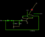
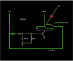
You have put the other end of the relay coil to 12V; the relay coil is rated for 5V and the transistor is taking too much current. The transistor base is also permanently tied to ground- that is not correct. The 12V source on the left side is also connected to the ground...


Schematics are already showed in post #9 and #20. Your schematic is veryyyy different than those schematics. Some resistors are missing.


I think I figured it out... the CLK gives half second 12V pulses, the relay coil remains energized for about a second, or if I dont switch off CLK
View attachment 130493

You have the right idea. My simulation had scope traces which showed the capacitor discharging slightly between pulses (CLK). If the pulses stop, the capacitor discharges completely.
Your second schematic has no bias resistor. It's a good idea to include one, so your transistor does not get ruined by overmuch current in the base-to-emitter junction.

If you do not have the transistor then the RLC circuit you will have will "ring" (i.e. oscillate) a bit and then will be always ON, meaning the relay is no more controlled.if I dont use a transistor for the circuit, I would need a reeeeally big capacitor dont I?

if I dont use a transistor for the circuit, I would need a reeeeally big capacitor dont I?

Yes, if you were to use the DRC pulse extender by itself, to drive the relay coil. By adding the transistor it allows you to use a smaller capacitor. You could go further and make the transistor a darlington combination, allowing an even smaller capacitor, if you wish.
There is probably a way to get a 555 timer IC to work in the mode you are discussing. It would also be based on the principle of a capacitor holding a charge between pulses.
