Continue to Site

Welcome to EDAboard.com

Welcome to our site! EDAboard.com is an international Electronics Discussion Forum focused on EDA software, circuits, schematics, books, theory, papers, asic, pld, 8051, DSP, Network, RF, Analog Design, PCB, Service Manuals... and a whole lot more! To participate you need to register. Registration is free. Click here to register now.

Need Help on how to build 7 - Segment Display circuit with Series of LED's

Status
Not open for further replies.
mister_rf

I find this very helpful. I've also done a similar drawing but, this one is so useful and easy to follow.

Thanks so much.. barbaro

---------- Post added at 13:13 ---------- Previous post was at 12:39 ----------

Hi mister_rf

The above minimum connections list, I noticed that you don't have any connections on IC 74192 - Pins 15,1,10 and 9. Should I also take it out on my connections?

Please advise...

Thanks,
Barbaro
 

Inputs A, B, C, D (pins 15,1,10,9) are used only for parallel load.
Parallel load capability permits the counter to be preset to any desired number. Information present on the parallel data inputs is loaded into the counter and appears on the outputs when the parallel load (Preset/load) input is LOW. This was needed for the 24 sec countdown. At this time we can ignore this function keeping pin 11 high level (+5V).
 

mister_rf

I'll ignore the Inputs A, B, C, D (pins 15,1,10,9) for now and kept ready for the next circuit with the 24 shot clock.

Thanks.
 

hello mister_rf

I really haven't had the chance to look into the schematic on the weekend but, I briefly took a try on the above late Friday night ignoring Inputs A, B, C, D (pins 15,1,10,9).

I had a weird result not giving me the proper counting. It is still only giving me 6, 7 and 8. When I press the switch B1, it should give me count #1 after pressing the reset button (displaying no. 8 figure) but it goes to seven right away and when you press the switch again, the LEDs blinks and when you press B! one more time, it displays the no. 8 figure but couple of the segments dims a bit.

Same scenario as B2. I've also experimented moving the +V line from the 7 segment and connecting it to the output of the LM7805 volt regulator and it give's me a default no. 2 when i press teh preset button B3. And when I press B1, it gives me a no - 5, 4, 6 or 9. B2 give's me no. 7, 3 and 5.

I checked all connections between the 74LS47 and 74HC192 are correct based on what you have given.
So, for some reason, it's coding it wrong. Is it possible, the two IC's not compatible or should I use a BCD counter?

Please advise ASAP.

I appreciate it very much.

barbaro
 

At least one connection missing between the two circuits. Reset button should give you some 0 on the display. I assume there’s a problem in the breadboard, due to the internal loose connections for the circuits. You need to test continuity for those wire using a multimeter.
 

mister_rf,

No, reset button doesn't give me some zero "0" on the display it gives me the number "8", I'm using the 4 colour telephone wires as my lines. I'll check the contuinity to all the wires on a multimeter.

Yes, at least one connection missing No. 1, for some reason, if I try move the +V line from the 7 segment to the output (leg no 3) of the LM7805, it shows the no. 1 display but it blinks and it give's a weird display before it goes to no 2 display when you press the reset button.


Thanks.
 

There’s no problems related to the display power supply. You should keep a 9V for the LEDs in order to have the correct voltage.

You need to use a multimeter or need to consider making a small and simple logic probe in order to examine the logic states at a particular point in the electronic circuit.
 
Last edited:
Hi mister_rf,

Is there any possibilities that the IC's 74ls47 and 74HC192 could have been discharged / decoded if by any chance I had touched the pins? The reason I say that it's because there was a time that I pulled the IC's out of the bredboard and I must have bent the pins and I tried to straighten it out.

However, I will need to consider making a small and simple logic probe in order to examine the logic states at a particular point in these IC's with a multimeter.

Please advice.

Thanks,

Barbaro
 

No way, those circuits have a more robust design to support small energy surges (not for lightning strikes or heavy-duty inductive surges :grin: ) just for a normal handling, so you can touch the pins without creating any problems.
 

mister_rf,

It's been a while that I was off to this project of mine.

LAst night, I was able to double check my connections again and figured that my segment "d" and "e" lines are interchanged. So, I got that corrected.

I tried disconnecting the capacitor on teh swicthes because it's not giving me proper counting. So, now it is counting up / down but only counting 1,3,5,7,9 and it looks like only add numbers.

Do you foresee any issue here with why it's only counting add numbers?

Please advise...

Thanks,
barbaro
 

Maybe there’s lose wire between pin 7 on 74ls47 decoder and pin 3 on 74ls192 counter side.
Try to do some test without this wire connected. If you will obtain same errors on counting, need to reposition the circuits into the breadboard. Otherwise reconnect this wire and start disconnect pin 1 on decoder side, repeat test, next reconnect wire, and repeat all steps by disconnecting pin 2 and later pin 6.
 

Hi mister_rf,

I did all the test and it's all OK. The counter is working and counting from 0,1,,2,3,4,5,6,7 skipping 8 and then dsiplays 9. This is on the count-up switch. Also, this is when I disconnected the capacitor. I left the capacitor on count-down switch but it's only displaying 0, 2, and 6 but it's bouncing.

What else should I do to make the counting right for up and down and properly displaying the correct increments or decrements by ones.

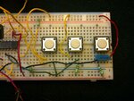
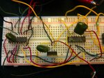
Please teake a look at the current circuit images and let me know your best recommendation. could you let me know how to test the current voltages if that's what causing the problem? or did I connected the wires incorrectly on the reset and on the switches? Should I change the switches itself?
 

What’s the value for the capacitor? Use small capacitors starting from 10nF up to 47nF (need to test in order to find the right value).
 

Please review the attached images....

Thanks,
Barbaro
 

Attachments

  • breadboard connections_Aug3A 005.jpg
    breadboard connections_Aug3A 005.jpg
    1.6 MB · Views: 125
  • breadboard connections_Aug3A 006.jpg
    breadboard connections_Aug3A 006.jpg
    1.7 MB · Views: 120

mister_rf,

The values for the capacitor is 47nF as you have previously recommended.

---------- Post added at 11:13 ---------- Previous post was at 11:10 ----------

Please find attached images...
 

As I have mentioned before, one of the problems with is that any mechanical pushbutton exhibits a phenomenon known as "contact bounce." To prevent this and obtain single digital pulses, we need to include with the switch a digital circuit that will react to the first contact closure, but will ignore subsequent contact bounce . We therefore may simply use a CD4093 Schmitt NAND gates, a resistor and a capacitor.
Now you need to add for UP and DOWN two circuits like this:
 

Attachments

  • debouncing circuits.GIF
    debouncing circuits.GIF
    6.6 KB · Views: 110

Hi mister_rf

I have the two 4093's now, could you please let me know the pin connections in an illustrationlike what you did with the rest of the circuits, you've indicated 1, 2, and 3 on the first IC and 4,5,6 on the other, are those the pins I hould be connecting to or no? the 4093 Ic's are 16 pins IC.

Pleas advise.

Thanks,
barbaro
 

I think CD4093 has 14 pins,
**broken link removed**
:-D

There are two possibilities here:
 

Attachments

  • Debouncing circuits v2.JPG
    Debouncing circuits v2.JPG
    106.9 KB · Views: 102

I think CD4093 has 14 pins,
**broken link removed**
:-D

There are two possibilities here:

hi mister_rf

you are right, the 4093, its only 14 pins but i just need to know the pin connections to the switches. I know the connections from the 47HC192 IC which is from the up and down - pins 4 and 5. when you say there are two possibilities, what do you mean by that? can you give me the illustration schematic?

Please and thank you.

Barbaro.

---------- Post added at 22:06 ---------- Previous post was at 22:02 ----------

hi mister_rf

Sorry, i missed the diagram you sent above. Anyways, what is the 40194? is that supposed to be what i have now as 47HC192?
 

Yes, ''40193''/''40192'' just an idea for the connection to be used for. In this case 74HC192. We didn't change the BCD counter, you got the idea for the circuit, as I understand some typo error like ''47HC192''= 74HC192. :-D
 

Status
Not open for further replies.

Part and Inventory Search

Welcome to EDABoard.com

Sponsor

Back
Top