Continue to Site

Welcome to EDAboard.com

Welcome to our site! EDAboard.com is an international Electronics Discussion Forum focused on EDA software, circuits, schematics, books, theory, papers, asic, pld, 8051, DSP, Network, RF, Analog Design, PCB, Service Manuals... and a whole lot more! To participate you need to register. Registration is free. Click here to register now.

Need help building a FM transmitter

Status
Not open for further replies.
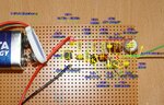
i ll post the screenshot 2mrw...

I dont have the freq counter to check the freq...

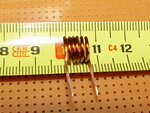
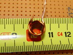
Dats the big problem and i use a enamel wire that i think too big in diameter...
 

I have tested :lol: by using two sets of coils each 6 turns/8mm diameter, one coil with 0.5mm wire, the other using 1mm wire, and the results doesn’t change too much. Try consider to increase the number of turns for the coil, up to 6-7. See the video:

 
Last edited:

i have uploaded a video of my design here

m.youtube.com/watch?gl=US&hl=en-GB&client=mv-google&v=jvuPqjh28FA

and Mister bro can you give the link of this video yu embeded...
 

Try not to waste the PCB area. :-D
You have there place to use it for 10 transmitters.
See some example how to arrange a layout for the transmitter.
Use a coil with 6 turns, coil diameter = 8-9 mm, wire diameter = 1 mm.
 

Attachments

  • coil 1.jpg
    coil 1.jpg
    390.7 KB · Views: 92
  • pcb 1.jpg
    pcb 1.jpg
    1.4 MB · Views: 80
  • pcb2.jpg
    pcb2.jpg
    503.6 KB · Views: 79
  • coil 2.jpg
    coil 2.jpg
    383.1 KB · Views: 79

The connections on the PCB should be identical to the circuit diagram, if you take time to reposition the components carefully you will reduce the used surface area of the PCB.
The embedded video link:
‪Mini FM transmitter‬‏ - YouTube
 

Attachments

  • FM sch.JPG
    FM sch.JPG
    173.4 KB · Views: 76
  • pcb + sch.JPG
    pcb + sch.JPG
    403.2 KB · Views: 83
I have tested the FM transmitter using a new coil, similar characteristics you have used, and for results the output generated frequency outside the broadcast FM band, somewhere between 116Mhz to 122Mhz. My suggestion: go change for a new coil.


can yu tell me bro...how many turn should I use more or less to be in a fm band??? or can anyone tell the price of freq counter too...???
 

I wouldn’t recommend using a frequency meter to make the necessary adjustments. Signal too low and can result in misleading interpretation on harmonics of the fundamental frequency. I will do some test later and show you the results using such a small frequency meter.
Try to use for L1 coil= 6 turns/ 6mm diameter coil.
 

if u nt usin freq meter...den how I ll gt to knw that I m out of fm band and all..?? :confused
 

Transmitter can be adjusted for the correct frequency even without dedicated equipment, but the arrangement of components on the PCB must follow the simply rules shown in the previous photos. In these conditions respecting the number of turns and coil diameter, transmitter can be easy tuned in the frequency band required only using the trimmer capacitor.
 

Can you give another ckt diagram ...ill try that...because its nt working...:(
 

So which transistors should i use???
 

Hey, I'm building one of these too but i didn't want to make a new thread. I'm having trouble finding an 1-5p to 30p air trimmer but i found this one: Digi-Key Part Search and i was wondering if it would work as well. If you don't feel like clicking the link, its 5.2 to 30p. Also if someone has a link to a cheaper/better/exact/etc version id appreciate it.


Hello frnds...i want to ask can i use 56k instead of 68k coz i dnt have that..can i use ...
 

No bodys replying :strange.... can anyone tell can i make a coil by standard single solid wire ...???
 

Firstly, you have been asking for the electrete microphone load resistor. Strictly spoken, it depends on the microphone specification. I my view, 10 k would be more reasonable for most microphones than 68 k, which is written far above in this thread. Probably both values will work. Instead of bombarding others with questions, you may want to check which value is appropriate for your microphone.

Secondly, you ask about the coil wire. Bare or silver-plated copper can work as well, if the windings are clearly separated. A short between two windings must be strictly avoided, that's why most people prefer enamelled or "magnet" wire.
 

Status
Not open for further replies.

Part and Inventory Search

Welcome to EDABoard.com

Sponsor

Back
Top