Continue to Site

Welcome to EDAboard.com

Welcome to our site! EDAboard.com is an international Electronics Discussion Forum focused on EDA software, circuits, schematics, books, theory, papers, asic, pld, 8051, DSP, Network, RF, Analog Design, PCB, Service Manuals... and a whole lot more! To participate you need to register. Registration is free. Click here to register now.

Need chip to withstand surges at input to power supply

Status
Not open for further replies.

cupoftea

Advanced Member level 6
Joined
Jun 13, 2021
Messages
3,057
Helped
62
Reputation
124
Reaction score
139
Trophy points
63
Activity points
15,948
Hi,
We are doing a Full Bridge, 10-36vin, 32vout, 300wout, 125kHz.
The input will see surges to MIL-STD-1275E and also DEF STAN 61-005 Part 6.

The LTC4364 is the beefiest of all offTheShelf surge protectors, but isnt capable of handling these standards' surges. Do you know of any that do, or are we looking at a home brew circuit only?

LTC4364

MIL-STD-1275E

DEF STAN 61-005 Part 6

 

Sounds way too complex compared to the MOV's to limit to 135V abs max Vin, and then the booster designed to handle 135V - but boosting to 38 - 40V and then the down converter rated to 150V ( pwm reduce for Vin > 38V )

a lot less parts, a lot less heat, simpler hence more robust, less control, lower BOM, smaller, easier to make ....
Thanks, but sorry i should have said we dont want MOVs in there, for reasons you have already disclosed about them.
I did like your previous idea about the Dual Boost to 38V, and then the Full Bridge with 200V FETs...
Though the thing we like about the Surge_Buck is its simplicity, its just on/off controlled with hysteresis...and it only works during the transient.

As discussed though, the reverse polarity "thing" is going to be quite something...i wonder if we can just get away with a dirty great diode crowbarring a fuse.......but no, its likely the only allowable thing will be a load of back to back NFETs...all 200V rated.......Maybe though, we can do something with a relay that only gets turned on when polarity is correct.......we also have to think about inrush protection......Hmmm.....The SMPS is the easy bit...the surge/inrush/rev pol circuit is the biggest part.
 
Last edited:
Thanks,
we also have to pass injected voltage spikes to +/-250V as per MIL STD 1275E
MIL STD 1275E

...but we cant use TVS as they must not break over at <175VDC as that is the surge voltage...and woudl kill a TVS.
I am just wondering if a big input capacitor can quench these +/-250V transients. Reverse polarity protection could be done by thirthy x 600v SiC diodes in parallel i think..(woudl you agree?)....that also protects against the -250V transients.

To protect against the +250v transient i guess we have to just rate all the fets that see it to 300V+

The inrush limitation to DEF STAN 61 005 and MIL STD 1275E....demands less than 7 times nominal current...so we will need an inrush limiter....but that inrush limiter must be ok when its exposed to the 175vdc surge for 500ms.....Hmmmmm....?...and must be able to port the 33A of running current that occurs when vin is 12vdc
 

that 250V spike is nothing and would be easily dealt to by filter caps and the MOV's

more alarming is the start up voltage applied ...
--- Updated ---

and the long term 100V transient - also the reverse input spec - which calls for a relay ( 2 x 30A in // ) or bridge rectifier at the input ... or a load of N fets in the neg line ( after the i/p filter )

--- Updated ---

the chances of meeting MIL-ST-461 for EMC are almost zero if you have not done it before ( we have )

24dBuV, which is the noise floor for many measurement set ups
 
Last edited:
and the long term 100V transient
Thanks, we are hoping that is dealt with by our "Surge Buck", which already deals with the long term 175vdc surge.

that 250V spike is nothing and would be easily dealt to by filter caps and the MOV's
Thanks, but sorry, i just cant bring myself to use MOVs...so it'll have to be TVS's, or we'lll just rate the FETs to 300V......(they were rated to 200V anyway, for the 175VDC surge.)

more alarming is the start up voltage applied ...
Thanks, i must have missed that, there is a high voltage applied at startup?

Also, if the Automotive MIL power supply calls out a spec of "10-36VDC" input, then, does that really mean "12-36vdc" input, but "must tolerate an input of 10-12vdc, but need not give full power output when vin is between 10 and 12v"?...or should it be able to give full power (300W in this case), right down to 10V?
 
Last edited:

Hi,
We are doing a Full Bridge, 10-36vin, 32vout, 300wout, 125kHz.
The input will see surges to MIL-STD-1275E and also DEF STAN 61-005 Part 6.

The LTC4364 is the beefiest of all offTheShelf surge protectors, but isnt capable of handling these standards' surges. Do you know of any that do, or are we looking at a home brew circuit only?

LTC4364

MIL-STD-1275E

DEF STAN 61-005 Part 6
If you identify specific shortcomings of the fave part, can you (or LT apps eng) identify "augmentation" (think back to good ol' LM117 linear regulator, all the circuit configs to boost current, etc.)?
 
Well...i see your point, and coincidentally, the LTC7860 does a good "Surge Buck" action, but it only drives PFETs, so wouldnt be any good for our use. Unfortunately cant be augmented to use with NFETs.

LTC7860

The LTC7860 does inrush/short cct and overvoltage clamping all from one chip...so when we break all of those out into separate subcircuits, we are going to end up with an enormous power supply front end.
Customer will likely take one look and say...scrub it...we'll do the transient/surge protection at system level....either that, or they'll just call for simple "just switch it out" transient/surge protection, instead
 
Last edited:

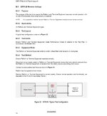
I wonder where reverse input protection has been added to the requirements? It's not in the original spec or in the quoted standards. MIL 1275E has negative spikes, but no reversed battery.
 
Thanks, as attached.
 

Attachments

  • def stan 61 005 _rev pol.jpg
    def stan 61 005 _rev pol.jpg
    213 KB · Views: 119
  • Like
Reactions: FvM

Agreed. There's however a considerable difference between a single-pole, single throw relays connecting only forward operation and a fail-safe pole reversal circuit.
 
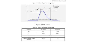
Hi, The DEF STAN 61-005 load dump surge is slow rising as attached..(taking 10ms to get up to 175V) .but is it always this slow?....i mean, if there are no loads on the 28V bus, then wouldnt it rise to 175V in a microsecond or so?

We are just thinking of having a BuckBoost converter at the supply front end, and bypassing this with say six pllel NFETs...but then switching out the bypass when the surge starts rising, and deal with the surge with the buckboost converter. The slow rising nature of the transient encourages us that we can switch off the bypass FETs in good time?

The Buckboost would give a constant 45V output......when the surge subsides back down, the input to the buckboost would go below 45V and so then the bypass FET internal diodes would then start conducting "backwards", at which time, we could switch the Bypass FETs back on, with little "Inrush" current going through them as they would only have a diode drop across them at the time that they are switched.. It all sounds so contrived though, as if "why are we doing this?".
 

Attachments

  • DEF STAN 61 005 PART 6 _LOAD DUMP.jpg
    DEF STAN 61 005 PART 6 _LOAD DUMP.jpg
    71 KB · Views: 97
Last edited:

Lots of interesting discussion being generated. Maybe I missed it, but has anyone proposed dealing with the 100V load dump by simply designing the main full bridge DC-DC stage to operate with Vin up to 100V? With sufficiently fast semiconductors, a 10:1 Vin range is not too challenging. You don't have to optimize for excellent efficiency at high Vin, since the surge won't last long enough for it to really matter. I'm assuming EMC during a surge is also not tested. It just has to survive while maintaining load regulation during the surge.

Main drawback is that many power components would need to have higher voltage ratings (biggest impact would probably be in the input caps). But no matter how you look at it, this PSU is going to end up being much chunkier than a commercial PSU with similar power specifications. But making existing components larger seems preferable to adding in completely new subsystems (like pre-regulating boost converters), IMO.
 
Status
Not open for further replies.

Similar threads

Part and Inventory Search

Welcome to EDABoard.com

Sponsor

Back
Top