Continue to Site

Welcome to EDAboard.com

Welcome to our site! EDAboard.com is an international Electronics Discussion Forum focused on EDA software, circuits, schematics, books, theory, papers, asic, pld, 8051, DSP, Network, RF, Analog Design, PCB, Service Manuals... and a whole lot more! To participate you need to register. Registration is free. Click here to register now.

Need a bit of help with a 12V 10A SMPS design using TL494

Status
Not open for further replies.
Got it crutschow! Thanks for that. I had never thought of it.

FvM - How do I calculate the value of the pull up? Should it be the standard pullups of around 47K? Also the Z-diode should be less than the Vgs rated in the FET's datasheet (which in this particular case is +/- 20V)? Also, if I use the Z-diode, I can eliminate R12 altogether. Am I right?
 

The pull-up should be as low as acceptable according to power dissipation, e.g. 470 to 1 K. When using a Z-diode to set the gate voltage, R12 is necessary to limit the diode and TL494 output current.

The z-diode solution is better to keep the gate voltage constant with varying input voltage. But z-diodes have relative high capacitance and will reduce the gate switching speed.

The present schematic shows an output current that can't be achieved with a 24V/3A transformer, as previously mentioned.
 

Oh! So if I were to reduce the switching speed, I'd have to go for an expensive inductor and if I were to keep it the same, I'd have to go for a bigger transformer which is again very expensive! :( Any ideas on how I can resolve this conundrum?

Also, the lowest Rds P-MOSFET I could find in a price range that is fairly acceptable was 62mR. This gives me a power dissipation of about 4W at 8A. Also this is the inrush current and not the normal operating current (which is about 5.5A. At which the power dissipated is about 2W). Not too sure if I'd still need a heatsink here.
The transformer size has nothing to do with the switching speed or the inductor size. The limit is that you can't get more power out of the regulator than the transformer can supply. For rectifier output the transformer should be derated by a least a factor of 1.6, thus the maximum power from the recitfier should 24V x 3A/1.6 = 45W. This gives a maximum converter output current of 45W/12V = 3.75A (assuming 100% efficiency). So for 5.5A output you need a transformer about twice as large as you have.

2W is probably marginal for a MOSFET in free air especially if the air inside the electronics module heats up over the ambient temperature. I would add a small heat-sink.
 

Right! This means that my transformer would have to be around 24V, 8A to give me a power output of 120W which is what is needed at the output (at 100% efficiency). In this case, I'm designing for a current draw of 10A. However, only about 5.5A of this will be actually used when the motor is in use. Is there a way I can limit the motor inrush current of around 8.8A or do I necessarily have to provision for that and in turn use a massive transformer?
 

The transformer is able to supply the two- or threefold current for e.g. 1 or 2 seconds. Rectifier and filter capcitors must be dimensioned for respectively higher current.
 

OK! Now if I design this SMPS for a 6A consistent load (where the peak current supplied is 6A), then it'll still be able to start the motor? Does that reduce the life of the transformer?
 

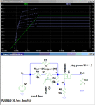
You could also add a current-limit circuit at the input to the TL494. Below is an example circuit with an adjustable limit (as shown by the current for various pot wiper positions). The P-MOSFET and BJT can be any with a sufficient voltage and current rating. This will also protect against accidental short circuits on the output.

Current Limit.gif
 

Thanks crutschow! This certainly helps.

I'm also evaluating a design based on the LM3150 by TI. It seems more simple and pretty much has the same set of specs as this one.
 

Hi crutschow, Can you please attach the simulation file for the above figure? I'm assuming its in LTSpice? How did you simulate the variable resistor?
 

Great thanks! I cannot seem to find a variable resistor in LTSpice though. Is that a custom component?

- - - Updated - - -

Actually dont bother. I found one on the LTSpice yahoo group! Thanks again!
 

Status
Not open for further replies.

Part and Inventory Search

Welcome to EDABoard.com

Sponsor

Back
Top