Continue to Site

Welcome to EDAboard.com

Welcome to our site! EDAboard.com is an international Electronics Discussion Forum focused on EDA software, circuits, schematics, books, theory, papers, asic, pld, 8051, DSP, Network, RF, Analog Design, PCB, Service Manuals... and a whole lot more! To participate you need to register. Registration is free. Click here to register now.

multiple SMPS Voltages

Status
Not open for further replies.
the output transistor generated the square wave.

---------- Post added at 06:57 ---------- Previous post was at 06:01 ----------

yes right,
the output transistor generated the square wave.

and next??
 

which terminology u r using ???? i mean Push-Pull, half bridge etc.....
 

i use konverter dc-dc topologi flyback...
the problem is the trafo...

how to test the trafo that i had return,is well or not????
any one can help me?

---------- Post added at 03:36 ---------- Previous post was at 03:01 ----------

there is no one can help me???
 
Last edited:

how to test it i'm newbie with osciloscope and function generator...
 

Hi again Dear Pol
do you have access to the function generator and oscilloscope ?
 

i think i didn't get the answer,
 

Hi dear pol
Sorry if my sentence wasn't clear . if you have access to an oscilloscope and a function generator , you can do below things :
1- use a capacitor in parallel with your inductor . ( thus , you'll make tank circuit )
2- then give your sine wave signal from your function generator across your tank circuit ( don't forget to add a series resistor with your input .)
3- measure the voltage across your out put ( see my attachment , please ) with your oscilloscope . try to change the frequency of your function generator until you see the voltage is going down . when the voltage across your out put decreased by 3 db thus it means that frequency is your resonant frequency .
4- Follow this formula : Fr= 1/2*pi*((LC)under radical ) and you know the value of your capacitor and you know the value of your resonant frequency and you'll find the value of your inductor simply .
Note : if you use a large value capacitor the result will given faster ( you won't need to change your input frequency very high ). ( but remember , don't use electrolytic capacitors , or if you want use them , use two electrolytic capacitor in series bu back to back .
RLC.JPG

Good luck
Goldsmith
 
Last edited:

i want to know that how can i measure that damped fequency through osciloscope or any other alternative. give me a example so that i can understand it
Hi again
For snubbers , there are many ways , but i want tell you a simple way :
build your circuit without snubber and then see the overshoots ( oscillations ) and measure the frequency of those damped oscillations , and then use an RCD or RC network , the has an Fo=1/2*pi*R*C and F0 should be about the frequency of those oscillations and you can select the capacitor randomly and then you'll find the R , simply ( remember that R should have high wattage , but not very high , it require a bit higher wattage that you can calculate it simply .)
Best Wishes
Goldsmith
 

Dear Muhammad
Hi
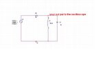
See below , please :
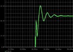
square wave.JPG
square circuit.JPG
Now i show you a wave form with zoom in .
square.JPG
So , what is the frequency of those damped oscillations ?
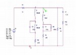
So i have designed an snubber network to improve those oscillations . see below , please :
square with snubber ( circuit ).JPG
square with snubber.JPG
Best Wishes
Goldsmith
 

i want to know that how can i measure that damped fequency through osciloscope or any other alternative. give me a example so that i can understand it

Use a single-shot mode and capture an edge of your signal. Zoom in on the ringing on the rising or falling edge. Measure the distance (time) from peak-to-peak (count the grid spaces, and look at the oscilloscope's setting for the horizontal axis... time/division), do a little algebra (hint: freq = 1/period), and get the target freq. If you are using a digital oscilloscope just use the vertical marker functions... it should read out the Δt directly, and possibly the frequency, too.... which is just 1/Δt.
 

my input range is 24v(jeep battery) which varies from 22V to 36V. and i need output of 30V. im confuse that what terminology i can use becz of this wide range. im confuse when 30V input and 30V ouput, boost transformer become buck, is this fine or not
 

Hi again
You can use , each topology that can increase the voltage . e.g boost converter , you'll be able to stabilize your out put at your desired value with a simple feed back . ( at boost converter , vout = vin/1-D.C D.C= duty cycle )
Best Wishes
Goldsmith
 

so i can use SG3525 to this stuff or suggest me any of the PWM controller
 

Try to use a simple LM2577 it is boost driver , although you can use SG3526N but , if your input is battery , you'd better to avoid from using that IC , because of magnetic dissipation .
Best Wishes
Goldsmith
 

i have did it,
i give input the function sine wave with 10 V peak to peak an give r = 1 kohm and c = 104 keramik capasitor.

but when i measure the output using osciloscop there is no the voltage,
i'm really confused.
 

Dear Pol
Hi again
Did you changed the frequency ?
if yes , from what range up to what range ?
Best Lucks
Goldsmith
 

100 k hz, and the output generated its about 3 v
 

Hi again
100 KHZ , and out put 3 volt , is that out put of your filter ? how much is your input ? try to increase the frequency up tp 2MHZ.
Best Wishes
Goldsmith
 

Status
Not open for further replies.

Similar threads

Part and Inventory Search

Welcome to EDABoard.com

Sponsor

Back
Top