Continue to Site

Welcome to EDAboard.com

Welcome to our site! EDAboard.com is an international Electronics Discussion Forum focused on EDA software, circuits, schematics, books, theory, papers, asic, pld, 8051, DSP, Network, RF, Analog Design, PCB, Service Manuals... and a whole lot more! To participate you need to register. Registration is free. Click here to register now.

[SOLVED] Multi independent PWM

Status
Not open for further replies.
X

Xenon02

Guest
Newbie level 1
Hello !

I have 24 high power LED drivers and each one of them requires independent PWM, is there any IC that has couple of independent PWM channels and I can program it using any interface ?
 

Check post#5 I said which driver I use .... I have said what driver it is.
Your point.

I don't know when you go to the store you already know what to buy ?
Yes! Because electronics parts are not chosen by mood, but by specifications.
It´s not like food.

Compare it with a screw. Let´s say I come to you asking for a screw for a heatsink. I´m sure you ask about the thread it needs to fit.
And wouldn´t you be surprised if I say I don´t know the thread, but lets just look for random screws.
There are different diameters, there are metric, there are imperial...

Screw = PWM
PWM specifications = thread dimensions

If I need a screw I first check out what "specifications / dimensions" I need, then I got to the shop to buy them.
That´s how I do it.

And after decades of professional electronics design, I can say: It works. No need for trial and error. Buying the right one. fits. done.


Klaus
 

555 timer IC with usual components produces a pulse train. Duty cycle is variable if you change the voltage at pin 5. (Also changes frequency to some extent.) An easy setup to experiment with PWM. It's a cheap IC, readily available. Operates up to 15V. Maximum current available 200mA.

Output from a photosensor probably needs conditioning.

555 duty cycle altered by resistive divider to gnd.png
 

Your lack of specs and overall purpose makes understanding your needs & choices impossible. These are essential communication skills if you wish to be a design engineer in a team. When you do not know the details, you must know the measurable effects of inputs and outputs. Your concept may be real or flawed.
 

And after decades of professional electronics design, I can say: It works. No need for trial and error. Buying the right one. fits. done.

Okey then.
Looking at the driver which is : AL1791AFE-13 It says that the PWM input for High signal must be : min 2,5V and Low signal must be : max 0.3V So the output of the PWM can be 3.3V why not or higher doesn't matter that much.
How much current is drained from the PWM pin of that driver ? Is unknown for me because the datasheet doesn't say anything about that sorry.
The resolution, well this is something I don't know, because I don't know how much of a difference it will be in the intensivity, may it be 16 bit ?
The frequency of that PWM, well the driver says that the max PWM frequency can be 4kHz which is not alot but maybe enough to do it. It also says it support 10kHz down to 1.0% which makes me thing what does it mean but ok.
Power supply, well the LEDs will be powered by 6V but I can make it higher or lower so no problem with that ... I can adapt it.
And the Interface, well this serial interface is ok from LT8500 but different options can also be cool to see.

Did I miss something more ?


Yes! Because electronics parts are not chosen by mood, but by specifications.
It´s not like food.

Yea but I am not sure if I will change that driver because something will not work so I have to find different driver, so different driver to the LED may or may not cause the change of the rest of the circuit so I wanted to just know how to find couple of PWM generators IC on my own ... But I only found LED driver constant current with PWM dimming which is not PWM generator as you can assume. I just wanted to know how to find it do I ask alot ...


555 timer IC

Not a bad idea though, but I needed something to control with microcontroller, I know there are digital potentiometers but I wanted to find something similar to LT8500 as KlausST mentioned in his first post.
 

Maybe a bit of a summary here :

1) You want a 24 channel bare pwm, each PWM individually settable for its duty cycle
2) Application lamp that will be dependent on environmental "brightness" (my word) ?
3) Several parts have been recommended.
4) You are still searching for 1) above for other offerings.
5) Control thru a serial link.....forum thinks .....?
6) Forum has no info on LED, its I & V requirements

Now I will do some guessing :

1) LM555 timer, 24 of them, out of the question due to obvious, parts count, freq and duty cycle error......
not synched so "patterns" of beat frequencies will be roiling around in the lamp, simply non starter.
2) Google will continue to be your friend in your search for other multi channel PWMs. Stating the obvious :)
3) The lamp will not be a $5 kind of lamp for sale, rather a high end lamp ? If so :

a. What sensors are used to control the lamp, how do you plan on handling that ?
b. Do you need a wireless solution to control lamp ?
c. Any sophistication in the patterns, eg. need for SW control intelligence ?
d. How will you handle brightness matching, by measurement or just sourcing matched LEDs ?

Lastly the PSOC mentioned earlier, it satisfies 24 (or more) channels, various digital serial link capability,
and are free to ignore all the other stuff on it, just dont use those resources. Note it also would, timing wise,
be a synchronous design. It also has capability when turned on or off, to do that, syncing all 24 channels
at once, so lamp does not start/die a horrible sequence of visual crap. Lastly PSOC also gives you Capsense
buttons if you need low cost user interface of some kind, and ability to work with a display if thats needed.

So I guess in short once you settle on more specifics we can all stop guessing and provide mo better help.....:)


Regards, Dana.
 
Looking at the driver which is : AL1791AFE-13 It says that the PWM input for High signal must be : min 2,5V and Low signal must be : max 0.3V
In my eyes ... this ... is the designer´s job. At least it is my daily job.

But the datasheet says much more:
It recommends
HIGH: 2.5V ... 5.5V
LOW: 0V .. 0.4V
Frequency: 500Hz .. 4kHz
It´s not clear to me why you missed the 5.5V, 0V, 500Hz ...

So the output of the PWM can be 3.3V why not or higher doesn't matter that much.
If this is information form the datasheet, please show me where you found it.
If it is YOUR information, then it helps nobody, it just brings confusion.

I asked about duty cycle range. There are limits by the device.
It´s your application, sou you need to decide what range you NEED. Not the "nice-to-have 0% to 100%. Where are your limits?

Also PWM resolution. Are you fine with 16 steps, 256 steps, 4096 steps? YOU have to decide this. Sooner or later, like it or not.
This is important to know for us to give you suitable advice.
Let´s say you want 500Hz with 32 steps resolution you could do all channels with a single microcontroller and software -PWM using (16kHz) interrupts. (Mentioned before).
But if you want 16 bits resolution with 4kHz, then a lot of microcontollers can´t generate a single one even with hardware PWM.
(= 65536 x 4000Hz = 262MHz, step frequency)

Please understand:
We don´t ask for information because we want to keep you busy, wek ask because we want to help you.

And please stay focussed. Tell facts, but don´t tell us things we don´t need to know. The human brain does not work like a computer.
Example: If I say: Don´t think about a pink elephant ... one automatically thinks about a pink elephant.
(You say you don´t want a LED driver. But see what happened: You´ve got a couple LED driver recommendations)

Klaus
 

AL1791AFE-13

1) That part is current regulated....thought you wanted bare PWMs ?

2) Your questions about current output the datasheet has extensive discussions about that
and of course you have thermal considerations to work on.

3) PWM high V, datasheet a little off, shows waveform traces at 5V, but then says max is 7
for a supply V of 30.... But logic level min "1" level is 2.5V for 12V supply......

Note PSOC PWM's can run well into the Mhz area.....


Regards, Dana.
 

But the datasheet says much more:
It recommends
HIGH: 2.5V ... 5.5V
LOW: 0V .. 0.4V
Frequency: 500Hz .. 4kHz
It´s not clear to me why you missed the 5.5V, 0V, 500Hz ...

1711401876607.png

Maybe this is not the place to read it so I wrote what was here.
If this is information form the datasheet, please show me where you found it.
If it is YOUR information, then it helps nobody, it just brings confusion.

I'll try to defend here myself.
So when I read that the PWM input of that AL1791AFE-13 must be min 2.5V so the output of the PWM generator can be 3.3V or 5V. I just said what Voltage level can be on the output.
I asked about duty cycle range. There are limits by the device.
It´s your application, sou you need to decide what range you NEED. Not the "nice-to-have 0% to 100%. Where are your limits?

I don't know what are the typical limits of the PWM. So it's hard to me to tell because I can tell 10%-90% limits but I don't know if this one exist nor it is to much.
I have no experience in it, so I hoped to check couple of datasheets to know the limits and choose one of many like with LED drivers I did the same thing tbh.

Some goes with the AL1791AFE-13 and his PWM input, how much can I change the PWM duty cycle. If I give 5% it might work incorrectly because there is no minimal time of the High signal. Ehhhh I don't know ;D
Let´s say you want 500Hz with 32 steps resolution you could do all channels with a single microcontroller and software -PWM using (16kHz) interrupts. (Mentioned before).
I don't know how it works. I imagined individual PWM in microcontroller using programming is to turn each input on (they will be slightly delayed) etc. So your methods are unknown to me and I should read something about it or see an example how it works. I am not that advanced in microcontrollers I guess as well with programming.
But if you want 16 bits resolution with 4kHz, then a lot of microcontollers can´t generate a single one even with hardware PWM.
(= 65536 x 4000Hz = 262MHz, step frequency)

I don't understand the math to be honest. 262MHz ?
Please understand:
We don´t ask for information because we want to keep you busy, wek ask because we want to help you.

I know but don't be angry at me but whenever I read something from your posts I just get the feeling as if I made the wrong thing for not knowing something or not knowing what it means at the first try.

I feel defeated because I don't know at this point what to achieve ... The resolution usually said how much the duty cycle changes (steps like 2% per step or something). So if 16bit is a lot because it is (65536 steps), the LT8500 is 12bit and is also okey (4056 steps). The 16 bit is indeed alot so 12bit or 10 bit (if something like that exist.

I've seen the propositions, but I don't much know about PSoC, about the 555 timer it has 1 output and I thought of more than 1 and to be adjusted by microcontroller and not by resistor manually using potentiometers.
I was looking for 1 IC that has PWMs so it takes less space in PCB.
And please stay focussed. Tell facts, but don´t tell us things we don´t need to know. The human brain does not work like a computer.
Example: If I say: Don´t think about a pink elephant ... one automatically thinks about a pink elephant.
(You say you don´t want a LED driver. But see what happened: You´ve got a couple LED driver recommendations)

Yea sure, as long as it is not constant current thing then yea.
AL1791AFE-131) That part is current regulated....thought you wanted bare PWMs ?

Dimming can be controller by PWM there is a special PWM pin. I don't want to regulate the brightness using resistors manually
2) Your questions about current output the datasheet has extensive discussions about that
and of course you have thermal considerations to work on.

I know the PCB design will require from me to somehow resolve the thermal problem, which I will somehow make it work.
3) PWM high V, datasheet a little off, shows waveform traces at 5V, but then says max is 7
for a supply V of 30.... But logic level min "1" level is 2.5V for 12V supply......

I mean I have couple of problem with this datasheet of AL1791AFE-13 because once it says max current output for using only and only 1 channel is 1A and then 1 page later is says 500mA using only and only 1 channel.

That's why I was only looking for how to find these PWM generators IC so if I change the LED driver I can somehow adapt and find new PWM generator if it must be done.
 

Can you describe what you are trying to see for a visual effect?
Constant brightness? ambient or LED in some 24 independent target zones. Then define the target to be reflected or detected. (There is a difference in emission and reflection)

If so, why PWM and not analog "light sensor" to LED driver which is so much easier without a central PWM control and uC complexity.
 

Maybe this is not the place to read it so I wrote what was here.
you read page 8. why not read page 7 section "recommended operating conditions".
The datasheet has 18 pages...

so the output of the PWM generator can be 3.3V or 5V.
This is true. Indeed any voltage higher than 2.5V will do. MIND: this is the SIGNAL voltage, not the POWER SUPPLY voltage.
But in post#24 you wrote: "o the output of the PWM can be 3.3V why not or higher doesn't matter that much."
--> 3.3V is not written in the datsheet. So where do you get the 3.3V information from?
--> also what does "not higher" mean ... while it clearly can be higher.
These - your sentences - makes it hard to understand what you mean.

****
I don't know what are the typical limits of the PWM. So it's hard to me to tell because I can tell 10%-90% limits but I don't know if this one exist nor it is to much.
I have no experience in it, so I hoped to check couple of datasheets to know the limits and choose one of many like with LED drivers I did the same thing tbh.
Again: It´s YOUR application. These informations you need to ask yourself, no datasheet can tell.
The range of duty cycle determines the range of LED brightness, and this is what YOU want to control. It was your idea to build an "adjustable light source". So YOU have to define what "adjustable" means for you.
Again: neither a datasheet nor anyone of us can (should) tell you how YOUR idea should work. It´s your idea.

****
I don't know how it works. I imagined individual PWM in microcontroller using programming is to turn each input on (they will be slightly delayed) etc. So your methods are unknown to me and I should read something about it or see an example how it works. I am not that advanced in microcontrollers I guess as well with programming.
No one of us is born with the knowledge how PWM works.
Thus there´s nothing wrong with not knowing it. It´s quite natural not to know it.
BUT you need to communicate with us what you know / what you need to know.

One can say: there is no dumb question ... on the other side it´s not wrong to find informations on one own. In my youth we had no internet, it was really hard to get infromations liek "how does a PWM work?". Nowadays one has internet. So use it. And if there still something is unclear, then refer to the document (communication) and ask a specific question.

PWM and microcontrollers:
Many microcontrollers have "hardware PWM" (description in the datasheet). It basically consists of a counter (variable bit width) and a comparator. The comparator output toggles a pin automatically (no code needs processed to toggle the pin. No processing power). But with software you are free to toggle as many port pins as you like. To get a fixed timing contol one uses interrupts.
Hardware vs software.

I don't understand the math to be honest. 262MHz ?
That´s rather basic stuff. 16 bits (counter, comparator) means 65536 steps (of duty cycle. of brightness). And if you want to run these 65536 steps 4000 times per second (4000Hz PWM frequency), then you need a counter frequency of 65536 x 4000Hz = 262MHz. Too much for a low end microcontroller.

Here in the forum are different people of different cultures with different levels of knowledge.
Some become upset if we explain basic stuff like "PWM counter frequency", others become upset if we don´t explain.
We only have the knowlege the psoter gives....

steps like 2% per step or something
You can control brightnes from 0% to 100% .. that´s it.
Now if you decide a step size of 2% ... then it´s no rocket science to calculate you need 50 steps (indeed 51 steps if you include 0% AND 100%)
Don´t get me wrong: This is what I expect from you to do these basic decisions and do this basic math.

Again: No one of us was born as an expert. We all made our mistakes, we all need (and still do) to learn.
Sometimes you decide 2% stepsize and find out you need a much finer granularity, the next day you decide 65636 steps and find out it was overkill.
We don´t know what you need.

Step size: for the brightness of light in a room .. I doubt there are many people that are able to destinguish between 10% brightness from 5 minutes to the next.
But I have done "precision light sources" to calibrate a light sensor. It needed better than 0.1% step size.

Klaus
 
you read page 8. why not read page 7 section "recommended operating conditions".
The datasheet has 18 pages...

You are right, sorry. I went straight into that huge detailed table. And I know it has 18 pages so I tried to find essential informations.
This is true. Indeed any voltage higher than 2.5V will do. MIND: this is the SIGNAL voltage, not the POWER SUPPLY voltage.
But in post#24 you wrote: "o the output of the PWM can be 3.3V why not or higher doesn't matter that much."
--> 3.3V is not written in the datsheet. So where do you get the 3.3V information from?
--> also what does "not higher" mean ... while it clearly can be higher.
These - your sentences - makes it hard to understand what you mean.

Yes I again messed it.
But first for the "not higher" there is "or" in between "not" and "higher". "It can be 3.3V why not. or higher" I add " like 5V".
Also I didn't specify 3.3V
BUT you need to communicate with us what you know / what you need to know.

Ok. I try as you can see.
I feel a bit overwhelmed to be honest but ok.

So
Nowadays one has internet. So use it. And if there still something is unclear, then refer to the document (communication) and ask a specific question.


Even though we have internet "Not everything on the internet is true or correct". So yes there is internet but reading datasheet and not understanding it the internet will not solve it.
To be honest I've been looking at some other LED Drivers than : AL1791AFE-13 and I don't understand the datasheets ... like : LM3404 - I am blind in looking for how to set the output current but says how to set Vmin and Vmax which I don't know why ... or PWM generator : LT8500 which says the PWMCK set to 25kHz will give me PWM out = 6.1kHz but doesn't say how to calculate the PWM out, there is the PWM width but I think this is the duty cycle ... Or the calculations without correction the *1/3 disappears this PWM_out = CHAN_N and with correction COR =/= 0 then PWM_out = CHAN_N * (2/3) * (COR*32)/64, with COR = 0 i still have *(1/3) but it dissapears welp. So many questions but I tried to find many informations.

I got so overwhelmed by the amount of information trying to find all information to give you trying not to get "this is the n-post and we get nothing".


Back to topic.

That´s rather basic stuff. 16 bits (counter, comparator) means 65536 steps (of duty cycle. of brightness). And if you want to run these 65536 steps 4000 times per second (4000Hz PWM frequency), then you need a counter frequency of 65536 x 4000Hz = 262MHz. Too much for a low end microcontroller.

Okey as I saw usually there are PWM 12bit, 10bit or 8bit, the 8 bit gives me 256 so each step gives me : 0.4% and 10 bit gives me : 0.1% or 0.098% I just rounded it up.
But I think 8 bit resolution will be fine. Because 0.098% isn't a big difference visually so 0.4% per step will be good.


Overall I've encountered many problems reading other datasheets from other LED drivers or I just don't understand them trying to find alternatives to : AL1791AFE-13, or trying to find other PWM generators which I failed to find because most of them are Constant Current Drivers well PWM generators are in LED drivers section somehow. But yea reading them I encountered many problems.
So right now I don't know what to tell you because now I don't know what I know and what not after reading datasheets ... So I wonder to abort this project and just give up on this stuff ... Cool that you had no internet but yea I am not you.
 
Last edited by a moderator:

If you go to youtube and search on "basic PWM", lots of videos on that topic.

Not to pile on but if one is involved in lighting photometry, human eye response,
a good read at bedtime. Discuss eye persistence, sensitivity, etc..


Regards, Dana.
 

Ok. I try as you can see.
You are doing a great job, now.
We (at least I) do understand much better now your worries.

****
Internet:
You are so true. There is a lot of wrong information around. And sadly errors are copied.
So what information you can rely on? My recommendation:
Most trustful informations are:
* from semiconductor manufacturers (datasheets, application notes, design notes..)
* from universities
* reputable designers
* descriptions which describe background informations, physics, math
Too many colors, too many different fonts is a warning sign for me.
Simplified schematics, short descriptions, too.

But I understand that "not that experienced people" look for simple solutions, simple explanations, short documents, easy to read documents. But life often isn´t that simple. And if one likes it or not, one can not ignore physics and math.
As a curious electronics designer I have to learn new things every day. But no, this isn´t true. It rather is:
As a curious electronics designer I like to learn new things every day. (what big difference three letters can make!)

LT8500 which says the PWMCK set to 25kHz will give me PWM out = 6.1kHz but doesn't say how to calculate the PWM out
It´s not 25kHZ, it is 25MHz! And it also says the math behind. 12 bits of PWM resolution means 4096 PWM steps. For one PWM period.
So counting repeatedly from 0 to 4095 ... with a counting speed of 25 million counts per second results in 6100 periods per second. = 6.1kHz.

But yea reading them I encountered many problems.
Happens to all of us. --> first try to find the solution (knowledge) on your own. Then discuss with us by referring the document you´ve read.

****
This all is no rocket science. No need to give up. Take your time. Let it settle. Read again the next day.
Stopping this project leaves a bit of frustration.
But digging through the dirt and getting your idea to work ... results in satisfaction.

****
Even for me your project sounds complicated. Why that much channels, why that many LEDs? Are the LEDs different color, different temperature of white?
Are they spread over a huge or small area? Are they used for photography, growing plants, other science, are they used as some kind of disply, or as ambient light?
How fast do you want to change brightness, what is your "input" for changing the brightness (sensor, data base, image...)

... in the end I´m aksing myself: Could you do it more simple?
Or should I recommend to divide your project in smaller parts:
First using a simple LED, a potentiometer and an amperemeter. To learn how your eyes work, how much current you need for a bright LED, how much current you need for a dim LED.
Then doing a simple PWM project for a single LED to get a feel for PWM, frequency, step size, flicker...
Learn how to control it, learn how the interface works, learn how to write code ...
Then next step to use three channels as RGB .. to get a feel for colors. A fixed color, then fading from one color to the other. To get a feel for how your eyes react.
Then next step to go more in direction of high power ... then higher channel count ...

I don´t know .. because I don´t know what you are looking for, what experience you have (about human eyes, colors, physics, math, eletronics, writing code) and what the aim of your project is.
We don´t know: is it your own hobby idea, is it a school project, is it your job to design light electronics, do you get payed for the effort...


Klaus
 
One consideration in coding is use a 24 byte buffer. When you need to change a PWM
check first its buffer value, if it is still the same NOP, no change to either PWM or buffer.
If its different value update PWM and buffer. That way instead of constant write activity
to PWM registers you only change the one needing a change. It should help avoid visual
artifacts created by constantly writing PWMs that cause short recycling of specific period/
cycle PWM is in, effectively restarting it. Unless you do it synchronously to the period either
thru HW or SW.

'One last, take a look at this Pulse Density Modulation component (available on PSOC). Its used
in lighting to create flicker free diming designs. And many other applications.

Regards, Dana.
 

Attachments

  • PrISM_v2_20.pdf
    509.6 KB · Views: 93
Last edited:

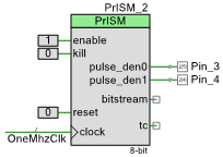
Instead of using PWMs as in my prior post I used density modulator component (PrlSM) inside PSOC
lib. Here is data being fed to each LED (continuously varying) :

1711553605782.png


And result :


Note I had to shoot video thru sun glasses because iPhone camera cannot handle the dynamic
range of led light output. But its artifact free dimming. Lastly using the onboard density
components uses significantly less onchip resources ovr PWM approach, surprised me.

Lastly lastly I wrote all PrlSMs with same data, if I had time I would do this with DMA out of a buffer,
so whole process is synched. I only wired up 5 leds because I am lazy.....


Regards, Dana.
 
Last edited:
Eye flicker reduction is an important aspect often ignored. This an interesting application of pseudo-random sequencing which can simulate any grey scale transition smoothly unlike PWM stepping. Our eyes are far more sensitive to changes than the general inaccurate sense of absolute levels. (Like IMHO 10 bits of resolution of low frequency changes compared to uncertainty of differences of absolute levels)


Here is Dave Van Ess's comments on signal processing in the density domain,
guru when he was at Cypress, attached.

This is what was used in post 35 for the density demo (only 5 LEDs done) :

1711568118801.png


Lastly there is a ton of app notes and white papers here on everything from eye response to
HW and SW design :


A 24 LED design takes about 50% of the UDB resources in the chip, leaving 50% for a lot of
other tasks, not too shabby.


Regards, Dana.
 

Attachments

  • Signal Processing in the Density Domain 1.pdf
    516.9 KB · Views: 95
  • Signal Processing in the Density Domain 2.pdf
    424.3 KB · Views: 90
  • Signal Processing in the Density Domain 3.pdf
    464.1 KB · Views: 86
  • Signal Processing in the Density Domain 4.pdf
    435.8 KB · Views: 91
  • Signal Processing in the Density Domain 5.pdf
    816.5 KB · Views: 83
  • 1711567911037.png
    1711567911037.png
    6.5 KB · Views: 92
Last edited:

TL;DR The parts missing for me were the effective rejection of peripheral eye motion sensitivity to 1 kHz flicker, aliasing effects of modulation density domain ( or time averaged duty factor) and the fact that PWM's are linear and our eyes and ears are logarithmic.
 
Last edited:

TS;RID (Too Short; Read I Did), those questions fully discussed on net and many sources.

@OP, Ignore the noise, I am prone to it and have brothers here with this as well. I think your
questions and path will get you solution(s), as I see already you have discussed. Do you know
yet what LED I & V requirements are ?

Regards, Dana.,
 

Do you know
yet what LED I & V requirements are ?

Yea hey
LED I have been provided with was exactly 6V/1A if it's what you are asking or perhaps the characteristics which I don't have yet, all I know are just 6Vf and 1A max.
But this is not important because the drivers are already selected, I just needed many PWM that's all. I didn't know how to make it with single microcontroller which usually had like 2-4 independent PWM ? So I tried to find a IC, but only found LT8500 so far, using an FPGA sounds interesting 1 chip which will make me 24 PWM, hmmm. Will think about that.
 

Status
Not open for further replies.

Similar threads

Part and Inventory Search

Welcome to EDABoard.com

Sponsor

Back
Top