Continue to Site

Welcome to EDAboard.com

Welcome to our site! EDAboard.com is an international Electronics Discussion Forum focused on EDA software, circuits, schematics, books, theory, papers, asic, pld, 8051, DSP, Network, RF, Analog Design, PCB, Service Manuals... and a whole lot more! To participate you need to register. Registration is free. Click here to register now.

[MOVED] SPI communication problem

Status
Not open for further replies.
data_read3 = data_read1 || (data_read2<<8); // read the received data from the buffer

pls checkout the OR ing Symbol to assign the data_read1 and data_read2 vaues to the data_read3.
 

hello Vbase I try today, but not getting 12 bit ADC data , only 8-bit receiving
 

Which ADC are you using?
Do the correction that benarjee pointed out, change || to |, try also
Code:
 data_read3 =((unsigned int)data_read1) | ((unsigned int)(data_read2<<8));
 

I am doing like this


Code:
data_read3 = (data_read2 | data_read1);

is that ok
 

I am doing like this


Code:
data_read3 = (data_read2 | data_read1);

is that ok

I'm not good enough to tell what is the right way for your compiler. The way you wrote it is likely to fail. Your code is replacing data_read2 with data_read1. You have to change one byte into int (cast) and shift it and then with or add below it the other byte, this way you get 16 bit int.
Try casting read1 and read2 like I did, or try casting only the byte 2 ;
Code:
data_read3 = (data_read1) | ((unsigned int)(data_read2<<8));
 

see my code

Code:
while ( !SSPSTATbits.BF );        // wait until the all bits received
 
SSPSTATbits.BF=0;

data_read1 = SSPBUF; // read the received data from the buffer

data_read2 = SSPBUF; // read the received data from the buffer
data_read2 = data_read2<<8;

dis_cmd ( 0xC0);

data_read3 = (data_read2 | data_read1);

Look at post #19 I've already corrected your code. You have to send a byte with the SPI load the returned byte to data_read1 , after that send another byte with the SPI and load the returned byte to data_read2 , then convert them into an int.

It looks like you don't want to disclose your whole code, it is difficult to analyze it otherwise.

- - - Updated - - -

see my code

Code:
while ( !SSPSTATbits.BF );        // wait until the all bits received
 
SSPSTATbits.BF=0;

data_read1 = SSPBUF; // read the received data from the buffer

data_read2 = SSPBUF; // read the received data from the buffer
data_read2 = data_read2<<8;

dis_cmd ( 0xC0);

data_read3 = (data_read2 | data_read1);

For some reason I can't read the top half of your code, could be my browser.
 

see my code

Code:
while ( !SSPSTATbits.BF );        // wait until the all bits received
 
SSPSTATbits.BF=0;

data_read1 = SSPBUF; // read the received data from the buffer

data_read2 = SSPBUF; // read the received data from the buffer
data_read2 = data_read2<<8;

dis_cmd ( 0xC0);

data_read3 = (data_read2 | data_read1);

I saw all the code that you sent in the email. I'm quite sure it is ok as long as you declared data_read1,data_read2,data_read3 as int
 

I am using AD7328 at reference 3VDC for reading input voltage with range +/- 10VDC, my problem is that I am getting full reading from 0 to 10Vdc on my LCD display but resolution is not good . when I change 1 volt my display also get change by 1 volt ,but not getting intermediate value
 

Hello I need to calibrate my ADC , can someone proved me code for calibrating 12-bit ADC
 

I am using AD7328 at reference 3VDC for reading input voltage with range +/- 10VDC, my problem is that I am getting full reading from 0 to 10Vdc on my LCD display but resolution is not good . when I change 1 volt my display also get change by 1 volt ,but not getting intermediate value


Question is not so clear. Please elaborate clearly?

- - - Updated - - -

Hello I need to calibrate my ADC , can someone proved me code for calibrating 12-bit ADC

Calibrating of ADC can be done by adjusting the analog input volatage step by step and monitor for the output volatges. If there is more variation you need to adjust the Vref.

The voltage deviation from ADC which you are getting for 0V is called offset error and the voltage deviation which you are getting for maximum input volatge is called gain error.

The calibration can be done through hardware itself no specific kind of code of required to achieve this.
Zero- and fullscale adjustment of digital instruments is often done by digital means, e.g. by applying calibration parameters stored in a nonvolatile memory. In so far some code is required to calculate the corrected measurement values. The mathematic behind this "two-point calibration" is quite simple.
 

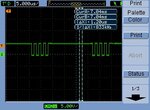
See how my 16-bit data transmitting over SPI using 8-bit buffer.

Is this a right way to communicate with 16-bit SPI device.
 

Attachments

  • NewFile0.jpg
    NewFile0.jpg
    34.1 KB · Views: 111
Last edited:

OK - the steps are:
- work out what the 16-bit command to the ADC should be (i.e. read or write, which register address, the data value to write etc) - this may be done elsewhere and passed in to your function
- lower the CS line
- put the top 8 bits of the command into the SSPBUF
- wait until the exchange completes (i.e. BF goes high)
- read the value in SSPBUF and save it (this also clears the BF bit) - this is the top 8 bits of the response
- write the bottom 8 bits of the command to SSPBUF
- wait until the exchange completes
- read the SSPBUF value - this is the bottom 8 bits of the response form the ADC
- raise the CS line
- construct the 16-bit response from the 2 8-bit received values above
There will be a small gap in the clock pulses between the first 8 bits and the 2nd 8 bits but the SPI interface will not care about that as the rising clock edge is what is used to read the data bit value.
Susan
 
Thanks Aussie Susan ,

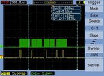
I successfully transmit 16-bit value, but I am not able to set my AD7328 ADC register value for reading multipal channel
 

Attachments

  • dataout and clock from contorller.jpg
    dataout and clock from contorller.jpg
    38.5 KB · Views: 105

I have no experience with that device and I'm not entirely sure what you are trying to do. However looking at the data sheet, and in particular the "Sequencer Operation" section (starting on page 25) you will see that the general sequence is that you write a command and simultaneously read back the previous result with each 16-bit transfer.
You don't show in your picture where the CS line is raised and lowered to delineate each command, but Figure 44 shows clearly that you need to follow the steps I've listed above exactly for each command, including lowering and then raising the CS line for each 16-bit exchange.
Susan


Yes I am using same figure 45 Sequence Flowchart
 

Status
Not open for further replies.

Similar threads

Part and Inventory Search

Welcome to EDABoard.com

Sponsor

Back
Top