Continue to Site

Welcome to EDAboard.com

Welcome to our site! EDAboard.com is an international Electronics Discussion Forum focused on EDA software, circuits, schematics, books, theory, papers, asic, pld, 8051, DSP, Network, RF, Analog Design, PCB, Service Manuals... and a whole lot more! To participate you need to register. Registration is free. Click here to register now.

[moved] root square summation of accelerometer axis pin using circuit

Status
Not open for further replies.

jitu_kumar

Newbie level 6
Newbie level 6
Joined
Dec 28, 2015
Messages
12
Helped
0
Reputation
0
Reaction score
0
Trophy points
1
Activity points
99
Hello everyone ;


I have a problem in root square summation of adxl335 accelerometer output pin.

accelerometer out put pin is x,y,z axis pin than i want to

Code:
R(out)=√(x[SUP]2[/SUP]+y[SUP]2[/SUP]+z[SUP]2[/SUP])
using circuit and after i want to read R pin of circuit using adc ..

if you have any solution and circuit than plz send me..
 
Last edited by a moderator:

If you wish to use an analog method...

A diode (or led or zener) is a component whose response is exponential. Amperes through the PN junction can be approximated as:
A = (b * V ) ^ c

Your sensor reading 'V' needs to be shaped to a narrow range (probably with an op amp), then applied to a diode. It admits a certain amount of current. Take the current reading across a resistor. (Expect to do a lot of work to adjust values so the output is the square of your input.)

Do the above for your 3 sensors. Sum (mix) all 3 sensor readings into an op amp. By reversing the above process you can convert A to V. Or else there is a square root circuit for op amps.

In fact if you can locate a squaring circuit for op amps, then that is probably easier to use than my diode method.
 

Precision squaring and square root circuits use OP amps and either analog multipliers or the exponential characteristic of bipolar junctions. If you estimate the BOM, you'll find out that it's probably easier to convert the three channels to digital and calculate the absolute value in software.
 

Precision squaring and square root circuits use OP amps and either analog multipliers or the exponential characteristic of bipolar junctions. If you estimate the BOM, you'll find out that it's probably easier to convert the three channels to digital and calculate the absolute value in software.

When I first saw this in the FPGA section I thought use something like this Maxim part, which simultaneously samples the 3 X, Y, and Z outputs of the accelerometer, but the OP asked for an analog circuit to do it and take the output of the circuit and use an ADC.
 

hi bradtherad ;

do you have any circuit diagram for than plz send me .

- - - Updated - - -

hi fvm ;


do you have circuit for that than plz send me .. because i i have but i dint find any multiplier ic like 434
 

but the OP asked for an analog circuit to do it and take the output of the circuit and use an ADC
Yes I know. But I permitted myself the comment that it's a rather inconvenient way to solve the problem, just look at the bill of material.

Considered you are somehow stuck to the analog computing solution and have only a large bag of OPs, transistors and resistors available then you can refer to the building blocks described in this classical National Semiconductor application note. https://www.ti.com/lit/an/snoa641b/snoa641b.pdf
The original date (1969) calls the time when this solutions have been preferable.
 

hi bradtherad ;

do you have any circuit diagram for than plz send me .

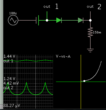
This is the basic concept.

8686582500_1455781581.png


Theoretically you can get the V-A graph to resemble y=x^2. (The exponent is not exactly 2 but it looks reasonably close.)

Notice the input must be within a narrow range, a few tenths of a volt. You'll have to work to bring your input signal within this narrow range.
 

i have a variable three input x,y,z . and its maximum 0-5v.
so i wnat to circuit that give me the output(O) like O=root(x2+y2+z2).

how its done using ad734.

- - - Updated - - -

i found the circuit but i dont know the ic 434 what is it ?

and shall it available in market ? and i search more but i cant find it .

if anyone know about it plz suggest me.

here is a photoe of circuit.circuit1.JPGcircuit2.JPG
 

433 and 434 are obsolete Analog Devices products. The circuit should work with recent analog multipliers as well.

- - - Updated - - -

The standard X*Y multipliers don't work, you need a X*Y/Z circuit like AD734, or something based on log/antilog, as previously suggested.
 

Status
Not open for further replies.

Similar threads

Part and Inventory Search

Welcome to EDABoard.com

Sponsor

Back
Top