Continue to Site

Welcome to EDAboard.com

Welcome to our site! EDAboard.com is an international Electronics Discussion Forum focused on EDA software, circuits, schematics, books, theory, papers, asic, pld, 8051, DSP, Network, RF, Analog Design, PCB, Service Manuals... and a whole lot more! To participate you need to register. Registration is free. Click here to register now.

[Moved] Please Help with first Pic project !!

Status
Not open for further replies.

acestu

Banned
Junior Member level 2
Joined
Mar 3, 2011
Messages
21
Helped
0
Reputation
0
Reaction score
0
Trophy points
1,281
Activity points
0
Hi,

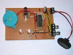
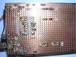
I am trying to construct my first Pic prpject on a veroboard but I can Not get it to work.

The project is the tune playing doorbell that is in the example files in ISIS 7 Pro.

As far as I can see I have soldered everything up right, however I am not sure if I am supposed to wire up the vss & vdd as they are not shown.

As soon as I attach the battery the 2 L.E.D.'s glow dimly.

Here are some pics:
Underside.jpgTopside.jpgDiagram.jpg

Thanks In Advance
Acestu
 
Last edited:

Re: Please Help with first Pic project !!

You'll need to post or upload your code for one of us to assist you.

A dimly glowing LED could indicate very rapid flashing, but with out your code it's just a hunch.

BigDog
 
  • Like
Reactions: acestu

    acestu

    Points: 2
    Helpful Answer Positive Rating
Re: Please Help with first Pic project !!

I am not sure if I am supposed to wire up the vss & vdd as they are not shown.
Yes, you must wire Vdd to +5V (assuming you have a 5V supply) and you must wire Vss to 0V.

EDIT: .... and you should connect MCLR through a 10K resistor to +5V, not directly.
 
  • Like
Reactions: acestu

    acestu

    Points: 2
    Helpful Answer Positive Rating
Re: Please Help with first Pic project !!

hi acestu,
connect pin5(Vss) to ground and pin14(Vdd) to +5V supply. The capacitors connected with crystals should be in the range of 20pF to 33pF. also, as hexreader said connect MCLR through a 10k resistor to Vdd supply. One more thing, use a breadboard when experimenting. And upload your code for further help.
 
  • Like
Reactions: acestu

    acestu

    Points: 2
    Helpful Answer Positive Rating
Re: Please Help with first Pic project !!

Hi,

Thank you for your replies, I will check out all those points tonight, I am also enclosing a copy of my code, I have loaded it into isis pro 7 and it seems to simulate perfectly.


thanks again
Acestu

View attachment Doorbell.rar
 
Last edited:

Re: Please Help with first Pic project !!

Hi,

I have now changed the caps to 22pf instead of 1nf, I have wired the MasterClear to +5v via a 10k resister, and I have wired VDD and VSS on the Pic, now
nothing works at all. What is the best way to troubleshoot ?, test power pins on the Pic with Voltmeter perhaps ?.

thanks
Acestu
 

Re: Please Help with first Pic project !!

What type of programmer/debugger are you using?

What are the messages during the program phase? Is the Flash verified are programming?

BigDog

---------- Post added at 19:50 ---------- Previous post was at 19:42 ----------

Are you using a PIC16F84 or PIC16F84A?

Have you downloaded the datasheet and errata for the device?

If not, I highly recommend doing so:

PIC16F84A Datasheet

PIC16F84A Errata

I do not see any configuration bit settings in your ASM file, so have you set them properly in MPLAB?

BigDog
 
  • Like
Reactions: acestu

    acestu

    Points: 2
    Helpful Answer Positive Rating
Re: Please Help with first Pic project !!

Hi Bigdog,

Thanks for the speedy reply,

The device is a pic16f84A and I am using a pickit3 to programme the device (compatible) with MPLAB software, I did a blank check first and it was verified, then I programmed the device and then read it, with the memory window open, I could see that the device memory had been programmed, however I don't recall setting any configuration bits, I thought the asm file set these for you.

thanks
Acestu

P.S. I do have the data sheet for the device
 

Re: Please Help with first Pic project !!

The device is a pic16f84A ....

You'll should change references in the ASM file from PIC16F84 to PIC16F84A

Code:
              LIST    p=16F84[COLOR="#FF0000"]A[/COLOR] ; PIC16F84A is the target processor

              #include <p16F84[COLOR="#FF0000"]A[/COLOR].inc> ; Include header file

The following is an ASM template specifically for the PIC16F84A, you can use it as a reference point:

16F84ATEMP.ASM
Code:
;**********************************************************************
;   This file is a basic code template for assembly code generation   *
;   on the PIC16F84A. This file contains the basic code               *
;   building blocks to build upon.                                    *  
;                                                                     *
;   Refer to the MPASM User's Guide for additional information on     *
;   features of the assembler (Document DS33014).                     *
;                                                                     *
;   Refer to the respective PIC data sheet for additional             *
;   information on the instruction set.                               *
;                                                                     *
;**********************************************************************
;                                                                     *
;    Filename:	    xxx.asm                                           *
;    Date:                                                            *
;    File Version:                                                    *
;                                                                     *
;    Author:                                                          *
;    Company:                                                         *
;                                                                     * 
;                                                                     *
;**********************************************************************
;                                                                     *
;    Files Required: P16F84A.INC                                      *
;                                                                     *
;**********************************************************************
;                                                                     *
;    Notes:                                                           *
;                                                                     *
;**********************************************************************


	list      p=16F84A            ; list directive to define processor
	#include <p16F84A.inc>        ; processor specific variable definitions

	__CONFIG   _CP_OFF & _WDT_ON & _PWRTE_ON & _RC_OSC

; '__CONFIG' directive is used to embed configuration data within .asm file.
; The lables following the directive are located in the respective .inc file.
; See respective data sheet for additional information on configuration word.


;***** VARIABLE DEFINITIONS
w_temp        EQU     0x0C        ; variable used for context saving 
status_temp   EQU     0x0D        ; variable used for context saving


;**********************************************************************
		ORG     0x000             ; processor reset vector
  		goto    main              ; go to beginning of program


		ORG     0x004             ; interrupt vector location
		movwf   w_temp            ; save off current W register contents
		movf	STATUS,w          ; move status register into W register
		movwf	status_temp       ; save off contents of STATUS register


; isr code can go here or be located as a call subroutine elsewhere


		movf    status_temp,w     ; retrieve copy of STATUS register
		movwf	STATUS            ; restore pre-isr STATUS register contents
		swapf   w_temp,f
		swapf   w_temp,w          ; restore pre-isr W register contents
		retfie                    ; return from interrupt


main

; remaining code goes here


		END                     ; directive 'end of program'

....however I don't recall setting any configuration bits, I thought the asm file set these for you.

You must manually configure the configuration bit settings for any PIC. There are two ways of accomplishing this task:

1. Using the MPLAB Configuration Bits Dialog, Menu: Config => Configuration Bits...

2. Using Assembler directives within the ASM file.

At minimum, you'll need to configure the Oscillator Configuration Bits and Disable the Watchdog Timer.

BigDog
 
  • Like
Reactions: acestu

    acestu

    Points: 2
    Helpful Answer Positive Rating
Re: Please Help with first Pic project !!

Thanks Bigdog,

I have fitted a dil socket to the veroboard so i can take out the device and programme it again on a breadboard, thanks for the template, I will have a look at that now and let you know how i go on.

cheers
Acestu
 

Re: Please Help with first Pic project !!

To configure the configuration bits within the ASM file, reference the following line of code from the template:

Code:
	__CONFIG   _CP_OFF & _WDT_ON & _PWRTE_ON & _RC_OSC

; '__CONFIG' directive is used to embed configuration data within .asm file.
; The lables following the directive are located in the respective .inc file.
; See respective data sheet for additional information on configuration word.

The appropriate "AND" masks for the above can be found in the device specific INC file.

I usually add this file to MPLAB's Project Window to reference while coding.

You can add the file by right clicking the Project Window and selecting add file and select the device specific INC file from MPASM Suite installation directory.

A portion of the P16F84A.INC containing the configuration bit masks:

Code:
; The following is an assignment of address values for all of the
; configuration registers for the purpose of table reads
_CONFIG          EQU  H'2007'

;----- CONFIG Options --------------------------------------------------
_LP_OSC              EQU  H'3FFC'    ; LP oscillator
_XT_OSC              EQU  H'3FFD'    ; XT oscillator
_HS_OSC              EQU  H'3FFE'    ; HS oscillator
_RC_OSC              EQU  H'3FFF'    ; RC oscillator

_WDT_OFF             EQU  H'3FFB'    ; WDT disabled
_WDT_ON              EQU  H'3FFF'    ; WDT enabled

_PWRTE_ON            EQU  H'3FF7'    ; Power-up Timer is enabled
_PWRTE_OFF           EQU  H'3FFF'    ; Power-up Timer is disabled

_CP_ON               EQU  H'000F'    ; All program memory is code protected
_CP_OFF              EQU  H'3FFF'

The following is a typical minimum circuit for programming/running a PIC device:

PIC 12F/16F/18F quick start

Since this is your first project you would most likely benefit from a set of excellent tutorials concerning PIC Assembly Programming:

**broken link removed**

The tutorials cover both Baseline and Midrange PICs using both Assembly and C languages, each lesson is in downloadable PDF form with the accompanying code in ZIP format.

The PIC16F84A is a Midrange PIC, so I would recommend studying at least the first three lesson of the **broken link removed**. If you have a breadboard, you can easily setup the hands on exercises contained in each lesson.

BigDog
 
  • Like
Reactions: acestu

    acestu

    Points: 2
    Helpful Answer Positive Rating
Re: Please Help with first Pic project !!

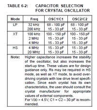
Thanks Bigdog that's really helpfull, do you know what the osc setting should be for a 1mhz external crystal because i beleive that after a certain frequency settings change.

thanks
Acestu
 

Re: Please Help with first Pic project !!

If you refer to the PIC16F84A Datasheet, Section: Oscillator Configurations, TABLE 6-2: CAPACITOR SELECTION FOR CRYSTAL OSCILLATOR , pg 22, 23:

Note: When using resonators with frequencies
above 3.5 MHz, the use of HS mode rather
than XT mode, is recommended. HS mode
may be used at any VDD for which the
controller is rated.


For the above quote and table, a 1MHz crystal should use the XT Oscillator designation.

Or if you are configuring the configuration bits from within the ASM file, use the "_XT_OSC" mask with the __CONFIG Assembler Directive.

I would also recommend using a decoupling or bypass capacitor of 0.1uF between Vdd and Vss, 5V supply and GND, as close to the PIC's pins as possible.

Put a 0.1uF decoupling capacitor on each positive supply pin, and put it as close to the chip on your PCB as possible

BigDog
 
  • Like
Reactions: acestu

    acestu

    Points: 2
    Helpful Answer Positive Rating
Re: Please Help with first Pic project !!

Thanks Again Bigdog, that was exactly what I was just going to look for, I have copied the pic and text, really usefull.

Just another Newbie question though if you don't mind, what do the decoupling capacitors do ?

thanks
Acestu
 

Re: Please Help with first Pic project !!

The power supply to your microcontroller should be well regulated and a smooth supply, to avoid another potential problem area.

However, even a well regulated supply and a well designed PCB is subject to Electromagnetic Interference (EMI) or noise, these small ripples on your supply lines can be the cause of erratic behavior and spontaneous reboots of the microcontroller.

The decoupling or bypass capacitor, literally forms a Low Pass Filter, bypassing any high frequency noise to GND.

Decoupling capacitor

**broken link removed**

Using Decoupling Capacitors

BigDog
 
  • Like
Reactions: acestu

    acestu

    Points: 2
    Helpful Answer Positive Rating
Re: Please Help with first Pic project !!

Hi again,

I have reprogrammed the device XT for osc then OFF OFF OFF, but when I connect the battery nothing happens untill I press one of the switches and then the 2 LED's come on and stay on. The other guy on here told me to change the crystal caps to 22pf, but now looking at your selection chart it recommends 100 - 150 pf so should I change them again ?.

Am I right in thinking that if these are not the correct value then the chip will not go through its cycle

Thanks Again
Acestu
 

Re: Please Help with first Pic project !!

I have reprogrammed the device XT for osc then OFF OFF OFF, but when I connect the battery nothing happens untill I press one of the switches and then the 2 LED's come on and stay on. The other guy on here told me to change the crystal caps to 22pf, but now looking at your selection chart it recommends 100 - 150 pf so should I change them again ?.

No, not necessarily.

The aforementioned table actually doesn't have a listing for a 1MHz crystal, but for a 2MHz crystal it recommends the 15pF to 33pF range.

I would stick with the 22pF caps you have installed, in actuality you should reference the crystals datasheet which usually specifies the appropriate capacitor value.

What configuration bit values are you configure as OFF OFF OFF?

Are you setting these values in code or the Configuration Bit dialog window in MPLAB?

Am I right in thinking that if these are not the correct value then the chip will not go through its cycle

You most likely have a clock signal, otherwise the activation of the switches would likely have no effect on the LEDs.

The easiest method to determine if the oscillator is functioning properly is to write a simple program to blink one of the LEDs with a one second delay.

What were the expected results of the program after initial power up? What are the sequence of events in the Proteus Simulation?

I would have to examine your code to see if there are any other possible issues.

BigDog
 

Re: Please Help with first Pic project !!

Hi again,

First I Edited the Header info on the asm file like you said and then

In the MPLAB console I set OSC to xt, WDT to off, PUT to off, and Cp to off I unchecked the little box that say's Config set by ASM file.

Then I reprogrammed after another build.

In Proteus the programme dosen't do anything until you press 1 of the buttons ie a button for the back door and a button for the front door, when a button is pressed a tune plays and an LED lights up, the 2 buttons have different tunes.

I think I will have to do like you say and programme with an led flasher ....

Thanks Again
Acestu
 

Re: Please Help with first Pic project !!

Hi again,

I have just written a programme to flash the 2 existing leds on the veroboard with a 1 second interval, powered up the board and they come on alternately but with a 15-16 second interval inbetween instead of a second so i guess something is wrong with the osc circuit, I am posting the new code for you to look at.

Thanks
Acestu
 

Attachments

  • 1SF.rar
    1.3 KB · Views: 75

Re: Please Help with first Pic project !!

Yes I programmed it again, checked the delay times and they are 1 second,
but when i power up the circuit still getting a 15 second delay, any ideas anybody please ?

thanks
Acestu
 

Status
Not open for further replies.

Similar threads

Part and Inventory Search

Welcome to EDABoard.com

Sponsor

Back
Top